Light emitting module and light receiving module
a light emitting module and light receiving technology, applied in the field of light emitting modules and light receiving modules, can solve the problems of reducing the efficiency of light collecting, the brightness of light emitted from the lens b>12/b> is not optimal, and the light emitted from the light emitting module b>10/b> may not efficiently emit light, etc., to achieve the effect of reducing the brightness of an emitted light, enhancing efficiency, and minimizing
- Summary
- Abstract
- Description
- Claims
- Application Information
AI Technical Summary
Benefits of technology
Problems solved by technology
Method used
Image
Examples
first embodiment
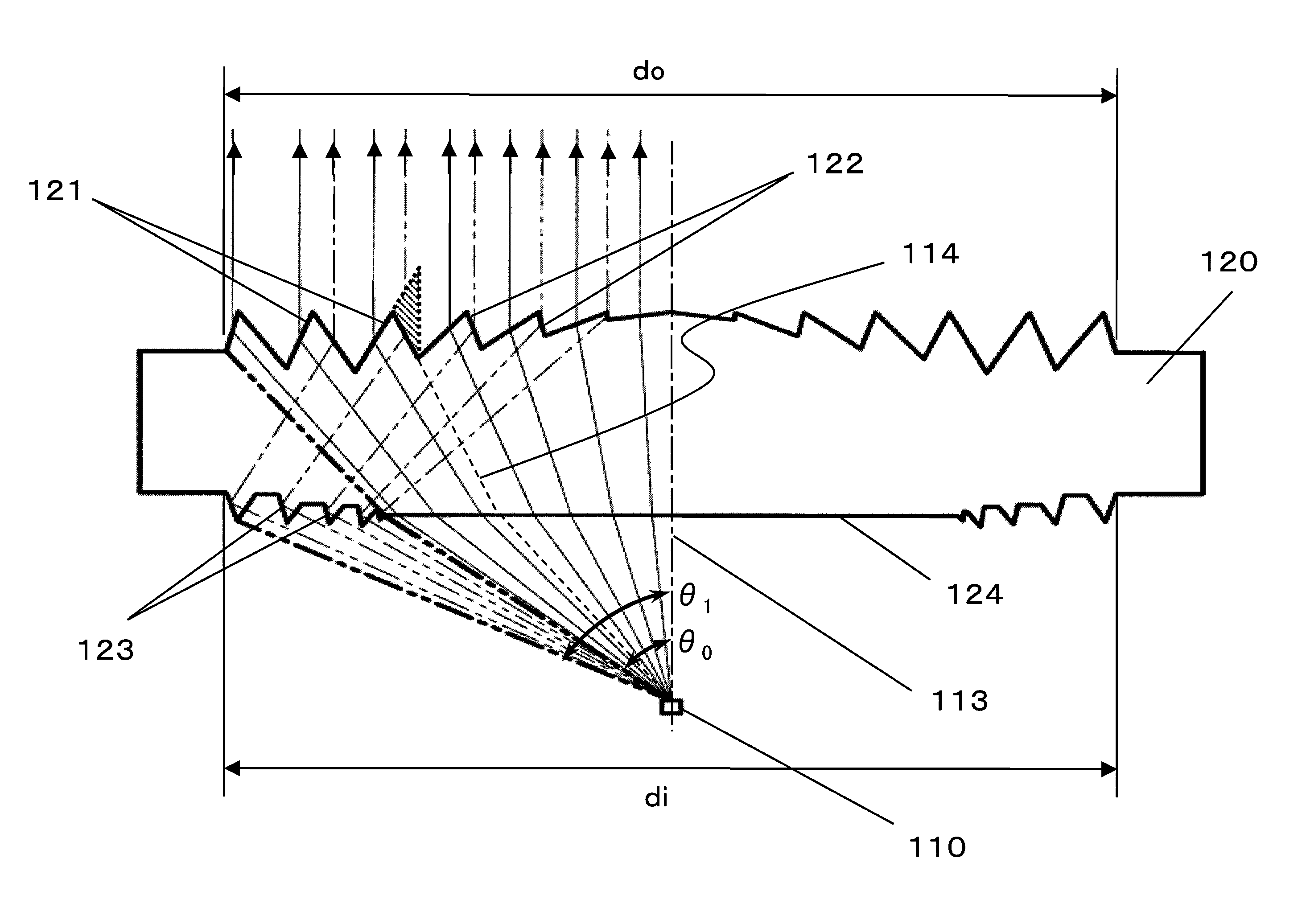
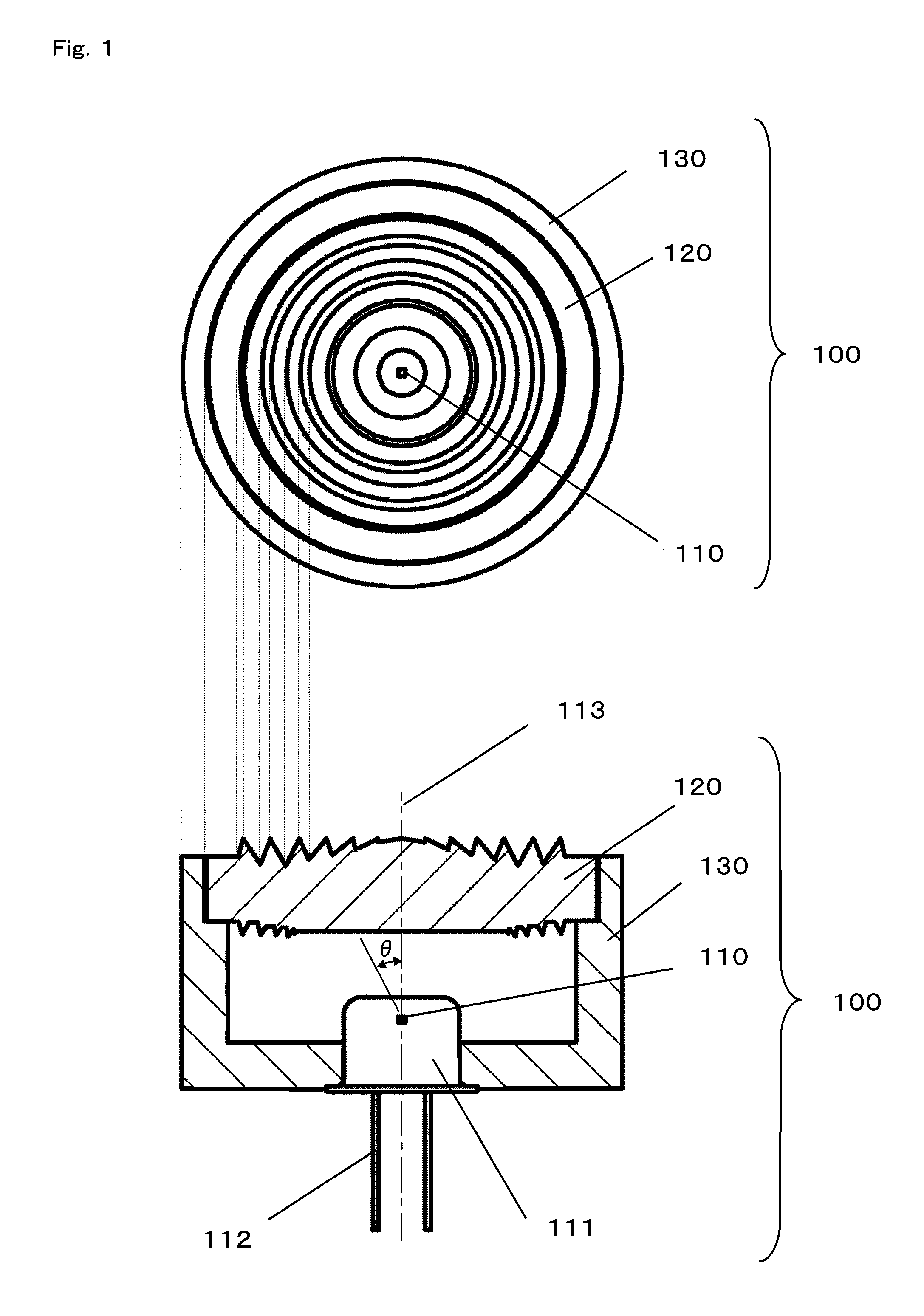
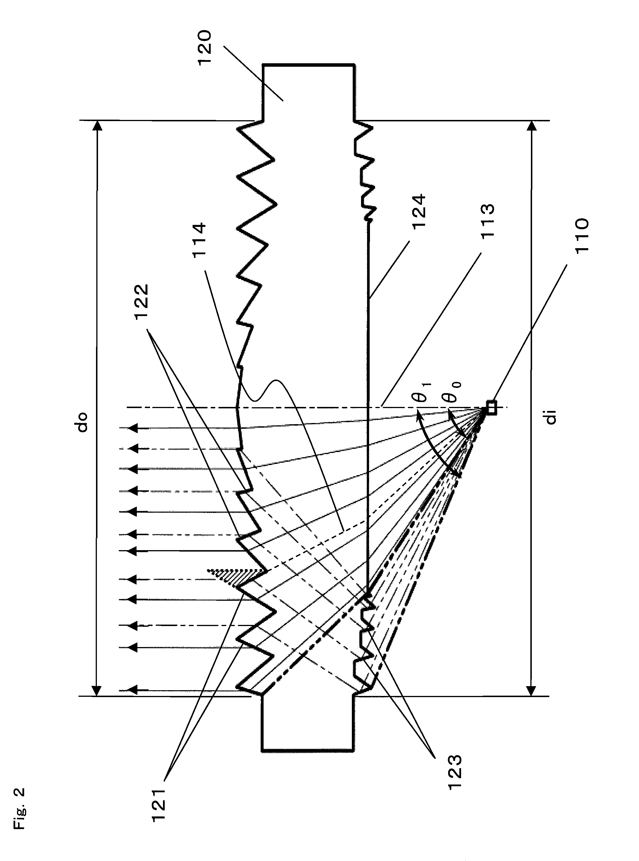
[0067]FIG. 1 is a top view and a side cross-sectional view of a light emitting module 100 according to a first embodiment of the present invention. FIG. 2 is a side cross-sectional view of a principal portion of the light emitting module 100 according to the first embodiment of the present invention.
[0068]As shown in FIG. 1 and FIG. 2, the light emitting module 100 mainly comprises a light source 110 and a lens element 120. As the light source 110, for example, a LED or a semiconductor laser is used. The light source 110 is accommodated in a package 111. The package 111 and the lens element 120 are fixed, in a housing 130, at such positions as to satisfy a predetermined positional relationship therebetween. A modulated electrical signal is supplied to the light source 110 through a terminal 112, and the light source 110 emits a light signal having, for example, its light emission intensity varied in accordance with the modulated signal, so as to spread out the light signal from an o...
second embodiment
[0092]In the first embodiment, a light emitted from the light source at an emission angle, ranging from θ0 to θ1, representing an angle between the optical axis and the emission direction is utilized so as to reduce variations in brightness of an emitted light, thereby realizing the light emitting module enabling highly efficient performance. According to the second embodiment, a light which is emitted from the light source but does not directly reach the lens element is utilized instead of the light emitted from the light source at the emission angle, ranging from θ0 to θ1, representing the angle between the optical axis and the emission direction.
[0093]FIG. 10 is a top view of a light emitting module 600 according to a second embodiment of the present invention, and FIG. 11 is a side cross-sectional view of the light emitting module 600 according to the second embodiment of the present invention. FIG. 12 is a side cross-sectional view of a principal portion of the light emitting m...
third embodiment
[0103]FIG. 19 is a top view and a side cross-sectional view of a light receiving module 2100 according to a third embodiment of the present invention. FIG. 20 is a side cross-sectional view of a principal portion of the light receiving module 2100 according to the third embodiment of the present invention.
[0104]As shown in FIG. 19 and FIG. 20, the light receiving module 2100 mainly comprises a light receiving element 2110 and a lens element 2120. As the light receiving element 2110, for example, a photodiode (PD) is used. The light receiving element 2110 is accommodated in a package 2111. The package 2111 and the lens element 2120 are fixed, in a housing 2130, at such positions as to satisfy a predetermined positional relationship therebetween. The light receiving module 2100 receives a light signal (for example, a light signal emitted from the light emitting module 100 of the first embodiment) from an optical wireless transmitter (not shown) provided so as to face the light receivi...
PUM
 Abstract
Description
Claims
Application Information
 - R&D
- Intellectual Property
- Life Sciences
- Materials
- Tech Scout
- Unparalleled Data Quality
- Higher Quality Content
- 60% Fewer Hallucinations
Browse by: Latest US Patents, China's latest patents, Technical Efficacy Thesaurus, Application Domain, Technology Topic, Popular Technical Reports.
© 2025 PatSnap. All rights reserved.Legal|Privacy policy|Modern Slavery Act Transparency Statement|Sitemap|About US| Contact US: help@patsnap.com


