Metallic Concave Reflection Mirror, Light Source and Light Source Apparatus Using the Same, and Lighting Circuit Thereof

a technology of concave reflection mirror and light source, which is applied in the direction of lighting and heating apparatus, instruments, optical elements, etc., can solve the problems of high-pressure discharge lamp light failure, relatively high material cost, and relatively expensive reflection mirror manufacture (b>2/b>′) manufacture, etc., to improve the curved surface precision of the concave reflection surface, reduce variations in brightness, and low heat-resistant property

Inactive Publication Date: 2008-02-21
PHOENIX ELECTRIC CO
View PDF9 Cites 2 Cited by
  • Summary
  • Abstract
  • Description
  • Claims
  • Application Information

AI Technical Summary

Benefits of technology

[0017] A first object of the present invention is to provide a concave reflection mirror for discharge lamps, at least the concave reflective portion of which comprises metal. A second object is to improve the curved surface precision of the concave reflective surface by the use of metal thereby to reduce variations in brightness. A third object is to attain a reduction in size and an increase in integration density of an overall light source apparatus by the use of such a concave reflection mirror. A subordinate object is to minimize scattering of mercury to the surroundings from a discharge lamp in case of explosion of the discharge lamp.

Problems solved by technology

Specifically, continuous application of a high pulse voltage of 15 kV would allow abnormal discharge to occur between an external lead pin (16) exposed from a high voltage side seal portion (18) of the high-pressure discharge lamp (10) and a metal portion located adjacent the external lead pin (16) (which corresponds to the neck portion of the concave reflection mirror when a metallic concave reflection mirror is used), resulting in a lighting failure of the high-pressure discharge lamp (10).
However, the concave reflection mirror (2′) formed of glass has possible problems as follows.
For this reason, the manufacture of the reflection mirror (2′) is relatively costly.
Since such crystallized glass is expensive, the cost of material becomes relatively high.
For this reason, a prolonged time is required for vacuum drawing in the evaporator oven, thus resulting in a relatively high processing cost.
The former remedy involves a problem of limitations on molding, while the latter has a problem associated with the cost, such as a considerably high cost of fluororesin coating.
Such a required insulation distance will greatly hinder a reduction in size and an increase in integration density of a projector.
For this reason, it is difficult for molding of the concave reflection glass mirror (2′) to be controlled in order to meet the curved surface precision requirements.
Stated otherwise, as long as the glass concave reflection glass mirror (2′) is used, there is a problem essential to the material used that variations in brightness are unavoidable.
Additionally, a problem has been pointed out that explosion of the discharge lamp (10), if it occurs, causes mercury within the discharge lamp (10) to be scattered to the around thereby to contaminate the surroundings, though it is a subordinate problem.

Method used


Image

  • Metallic Concave Reflection Mirror, Light Source and Light Source Apparatus Using the Same, and Lighting Circuit Thereof
  • Metallic Concave Reflection Mirror, Light Source and Light Source Apparatus Using the Same, and Lighting Circuit Thereof
  • Metallic Concave Reflection Mirror, Light Source and Light Source Apparatus Using the Same, and Lighting Circuit Thereof

Examples


Embodiment Construction

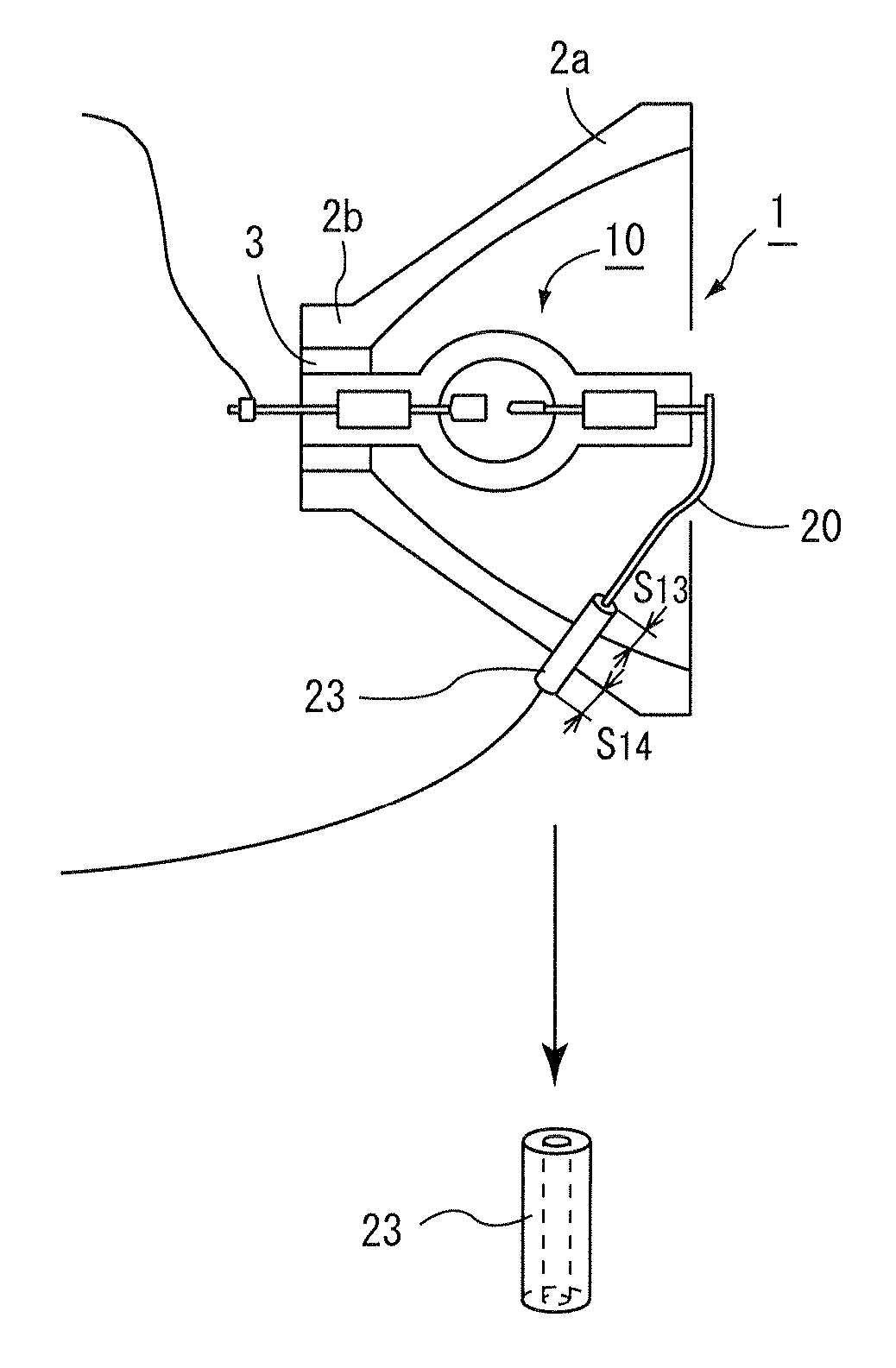
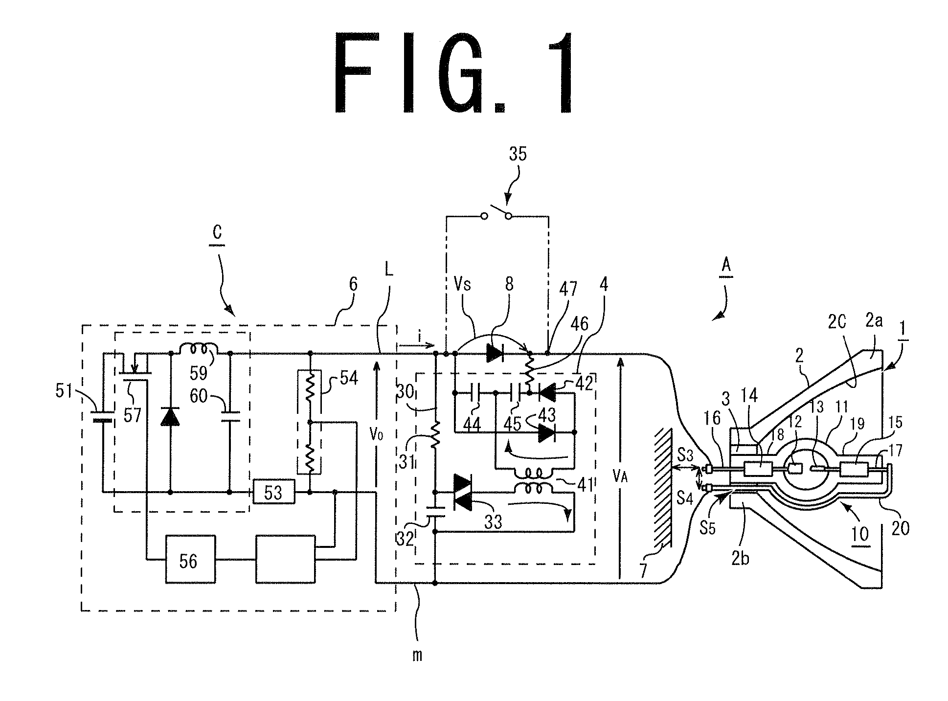
[0066] Hereinafter, preferred embodiments of the present invention will be described. FIG. 1 shows a light source (1) including a double-ended high-pressure discharge lamp (10) fitted with a concave reflection mirror (2) using metal for at least a concave reflective portion (2a) thereof, and a lighting circuit (C) associated therewith. This embodiment is a representative of arrangements of the type in which the high-pressure discharge lamp (10) fitted with the concave reflection mirror (2) has a seal portion (18) located on a high voltage side to be applied with a high voltage during an ignition phase as described earlier. The double-ended discharge lamp (10) is described herein as a representative of high-pressure discharge lamps. Besides, a single-ended discharge lamp may be used.

[0067] The high-pressure discharge lamp (10) used in the present invention has an envelope (11) formed from quartz glass, which is substantially insusceptible to thermal expansion / contraction. The envelo...


PUM

PropertyMeasurementUnit
d.c. voltageaaaaaaaaaa
thermal conductivityaaaaaaaaaa
breakdownaaaaaaaaaa

Abstract

This invention makes it possible to use a concave reflection mirror using metal in at least a concave reflective portion thereof for discharge lamps. The concave reflection mirror is characterized by including: a metallic concave reflective portion; and a neck portion for receiving therein a high voltage side seal portion of a high-pressure discharge lamp to be continuously applied with a d.c. voltage of 1000 V to 4000 V during an ignition phase, the neck portion protruding rearward from a central portion of the metallic concave reflective portion and being formed partially of an insulating member or entirely of an insulating material. The concave reflection mirror can have a concave reflective surface with improved curved surface precision thereby making it possible to reduce variations in brightness, use a multi-layered deposited film having a low heat resistance, and reduce the required cost considerably.

Description

TECHNICAL FIELD [0001] The present invention relates to a concave reflection mirror to be used as fitted on a discharge lamp, at least a concave reflective portion of which mirror is formed of metal, a light source apparatus using the concave reflection mirror, and a lighting circuit thereof, which are for use in information equipment, such as a liquid crystal projector, or video equipment, such as a projection television. BACKGROUND ART [0002]FIG. 2 shows a conventional light source (B) having a glass concave reflection mirror (2′) fitted on a high-pressure discharge lamp (10) for use in a liquid crystal projector. The high-pressure discharge lamp (10) is positioned with its optical axis substantially coinciding with that of the glass concave reflection mirror (2′) so as to generate a bundle of parallel rays or converging rays forwardly. Glass has been solely used as the material of such a concave reflection mirror (2′). [0003] Metal has not been able to be used for the concave ref...

Claims


Application Information

Patent Timeline
Patent Type & Authority Applications(United States)
IPC IPC(8): H01J5/16
CPCF21V7/22G02B5/10G02B5/0816F21V7/24F21V7/28
Inventor FUJII, TOSHITAKANAKAGAWA, ATSUJIIKEDA, TOMIHIKOFURUKAWA, HISAO
Owner PHOENIX ELECTRIC CO
Why Eureka
Try Eureka