
Single Transistor Floating-Body DRAM Devices Having Vertical Channel Transistor Structures and Methods of Fabricating the Same

a technology of vertical channel transistors and floating bodies, applied in the direction of transistors, semiconductor devices, electrical equipment, etc., can solve the problems of reducing memory storage capacity, deteriorating operation characteristics of dram cells, etc., and achieve the effect of improving the integration density of memory devices

Inactive Publication Date: 2006-11-09
SAMSUNG ELECTRONICS CO LTD
View PDF4 Cites 38 Cited by
  • Summary
  • Abstract
  • Description
  • Claims
  • Application Information

AI Technical Summary

Benefits of technology

[0013] Other embodiments of the invention provide methods of fabricating single transistor floating-body DRAM devices, which can improve the integration density of memory devices.
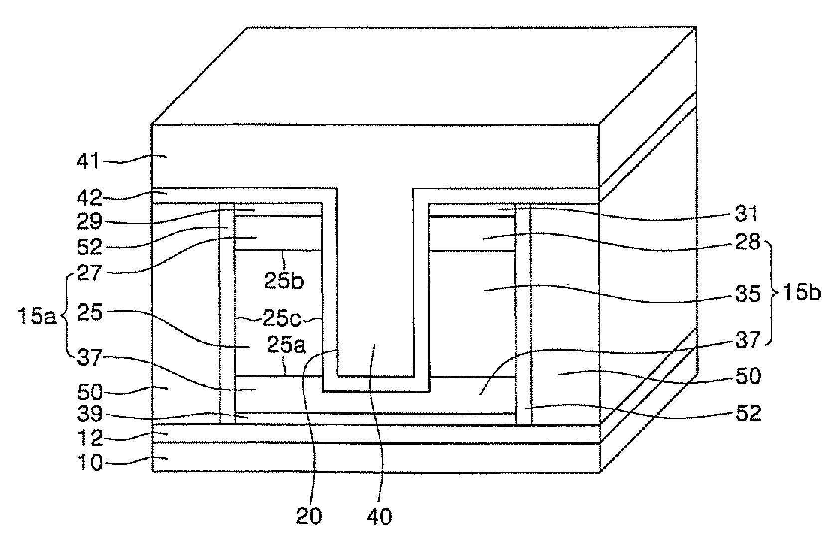
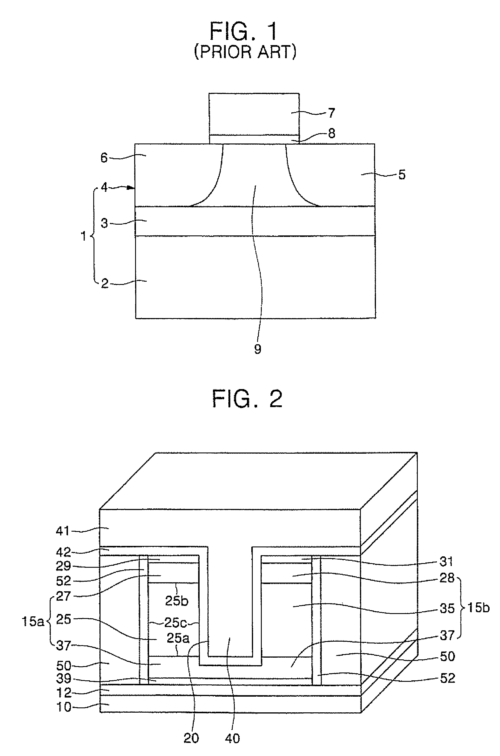
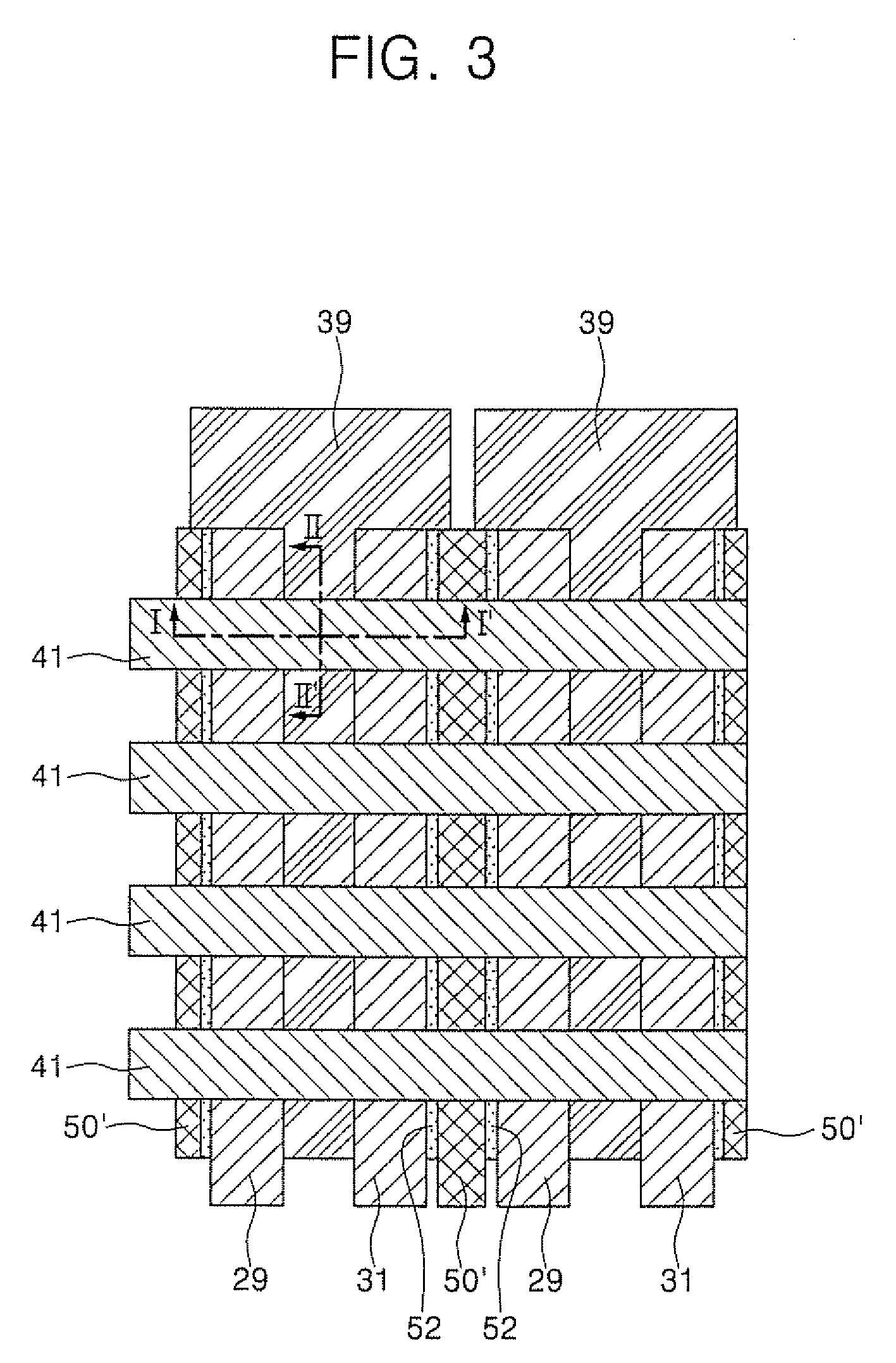
[0027] In another aspect, the present invention is directed to methods of fabricating single transistor floating-body DRAM devices, which are capable of improving the integration density of memory devices. The methods include forming a body layer on a semiconductor substrate having a buried insulating layer therein. Impurity ions of a first conductivity type are implanted into a lower region of the body layer, thereby forming a source region. Impurity ions of a second conductivity type are implanted into a region of the body layer that is disposed on the source region. Here, the second conductivity type is different from the first conductivity type. Impurity ions of the first conductivity type are implanted into an upper region of the body layer, thereby forming a drain region. The body layer having the source and drain regions is patterned, thereby forming a body layer pattern such that the buried insulating layer is exposed. The body layer pattern is patterned, thereby forming first and second floating bodies that are isolated from each other. Thereafter, a gate electrode is formed between the first and second floating bodies.

Problems solved by technology

As a result, the operating characteristics of the DRAM cell may still deteriorate.
However, a reduction in the number of the DRAM memory devices may result in a decrease of memory storage capability.

Method used


Image

  • Single Transistor Floating-Body DRAM Devices Having Vertical Channel Transistor Structures and Methods of Fabricating the Same
  • Single Transistor Floating-Body DRAM Devices Having Vertical Channel Transistor Structures and Methods of Fabricating the Same
  • Single Transistor Floating-Body DRAM Devices Having Vertical Channel Transistor Structures and Methods of Fabricating the Same

Examples


Embodiment Construction

[0038] The present invention is described more fully hereinafter with reference to the accompanying drawings, in which example embodiments of the present invention are shown. The present invention may, however, be embodied in many different forms and should not be construed as limited to the embodiments set forth herein. Rather, these embodiments are provided so that this disclosure will be thorough and complete, and will fully convey the scope of the present invention to those skilled in the art. In the drawings, the sizes and relative sizes of layers and regions may be exaggerated for clarity.

[0039] It will be understood that when an element or layer is referred to as being “on”, “connected to” or “coupled to” another element or layer, it can be directly on, connected or coupled to the other element or layer or intervening elements or layers may be present. In contrast, when an element is referred to as being “directly on,”“directly connected to” or “directly coupled to” another ...


PUM


Abstract

Single transistor floating-body DRAM devices have a vertical channel transistor structure. The DRAM devices include a substrate, and first and second floating bodies disposed on the substrate and isolated from each other. A source region and a drain region are disposed under and above each of the first and second floating bodies. A gate electrode is disposed between the first and second floating bodies. Methods of fabricating the single transistor floating-body DRAM devices are also provided.

Description

REFERENCE TO PRIORITY APPLICATION [0001] This application claims the benefit of Korean Patent Application No. 10-2005-0037244, filed May 3, 2005, the contents of which are hereby incorporated herein by reference in their entirety. FIELD OF THE INVENTION [0002] The present invention relates to semiconductor memory devices and methods of fabricating the same and, more particularly, to single transistor floating-body dynamic random access memory (DRAM) devices and methods of fabricating the same. BACKGROUND OF THE INVENTION [0003] In general, a DRAM cell includes one transistor and one capacitor, which are disposed on an active region. The DRAM cell uses the capacitor to store data in response to a “high-state” or “low-state.” Accordingly, the DRAM cell includes an area occupied by the capacitor. [0004] Recently, a DRAM cell that does not need a capacitor has been proposed. This DRAM cell is referred to as a single transistor floating-body DRAM cell (hereinafter, a ‘single transistor D...

Claims


Application Information

Patent Timeline
Patent Type & Authority Applications(United States)
IPC IPC(8): H01L21/8242H10B12/00
CPCH01L21/84H01L27/108H01L29/7841H01L27/1203H01L27/10802H10B12/20H10B12/00H10B12/48
Inventor HUO, ZONG-LIANGBAIK, SEUNG-JAEYEO, IN-SEOKYOON, HONG-SIKKIM, SHI-EUN
Owner SAMSUNG ELECTRONICS CO LTD
Learn More