Connection head structure of high pressure fuel injection tube

a high-pressure fuel injection and connection head technology, which is applied in the direction of special fuel injection apparatus, mechanical equipment, machines/engines, etc., can solve the problems of affecting the flow of fuel, so as to reduce the starting point of fatigue rupture, increase the tensile stress, and smooth the effect of the flow of fuel

Active Publication Date: 2010-06-15
USUI KOKUSAI SANGYO KAISHA LTD
View PDF37 Cites 24 Cited by
  • Summary
  • Abstract
  • Description
  • Claims
  • Application Information

AI Technical Summary

Benefits of technology

[0010]The present invention is carried out to solve the conventional problems, and is directed to propose a connection head structure of a high pressure fuel injection tube to avoid an interference between an annular flange and an opposing part by sufficiently maintaining a tube axial direction length of the connection head and to obtain a good sealability to prevent leaking during autofrettage processing with a high pressure of not less than 300 MPa.
[0015]In a connection head structure of a high pressure fuel injection tube according to the present invention, the connection head inner circumferential face includes a two stage tapered face having a cross section outline in a tube axial direction of the steel tube that broadens toward the aperture, and therefore almost no pocket (annular recessed portion) is created by plastically working the interior of the connection head; and therefore, the occurrence of cracks in the recessed portion of the pocket portion when forming the head, concerns of cracks occurring due to cavitation erosion by fluid pressure inside the head, and phenomena of a diameter enlargement of the inner diameter and an increase of tensile stress of the inner surface due to stress concentration resulting from creation of the pocket when forming the head are eliminated; the possibility of the connection head inner circumferential face serving as a starting point of fatigue rupture can be drastically reduced; and even when a thick-walled thin-diameter steel tube has t (wall thickness) / D (outer diameter)<0.3, an interference between the annular flange and the opposing part during connection can be avoided; normal functions of the high pressure fuel injection tube connection portion can be maintained when using an internal combustion engine; and it is possible to achieve a smoothing effect on the flow of the fuel combined with a more precise fuel injection because the pocket almost does not exist.
[0016]Also, a connection head inner circumferential face includes a two stage tapered face having a cross section outline in a tube axial direction of the steel tube that broadens toward the aperture, and the volume of the head can be reduced during formation with buckling even for a connection head having a relatively long axial direction length by appropriately setting the tube axial direction taper length and the taper angle; buckling is reduced by actively bringing a mandrel into contact with the head inner face during formation of the head by a method for forming the head using a mandrel, and the pocket is eliminated or reduced as much as possible; the sealability between the nozzle (seal plug) and the tubular body can be improved by ensuring a stable seal face or seal line during autofrettage processing performed on the high pressure fuel injection tube; and the stability and reliability of the seal is ensured even for autofrettage processing with a high pressure of not less than 300 MPa.

Problems solved by technology

However, it was ascertained that for the connection head structure of the high pressure fuel injection tube according to Japanese Patent Application No. 2007-61085 recited above, an axial direction length of the connection head cannot be sufficiently maintained; and unfortunately, there are concerns that the annular flange may interfere with the opposing part; a risk exists of deterioration of the sealability due to axial misalignment of the nozzle (seal plug) and the tubular body in the case where autofrettage processing is performed on the high pressure fuel injection tube; and in particular, for autofrettage processing with a high pressure of not less than 300 MPa, there are concerns that leaking unfortunately may occur.

Method used


Image

  • Connection head structure of high pressure fuel injection tube
  • Connection head structure of high pressure fuel injection tube
  • Connection head structure of high pressure fuel injection tube

Examples


Embodiment Construction

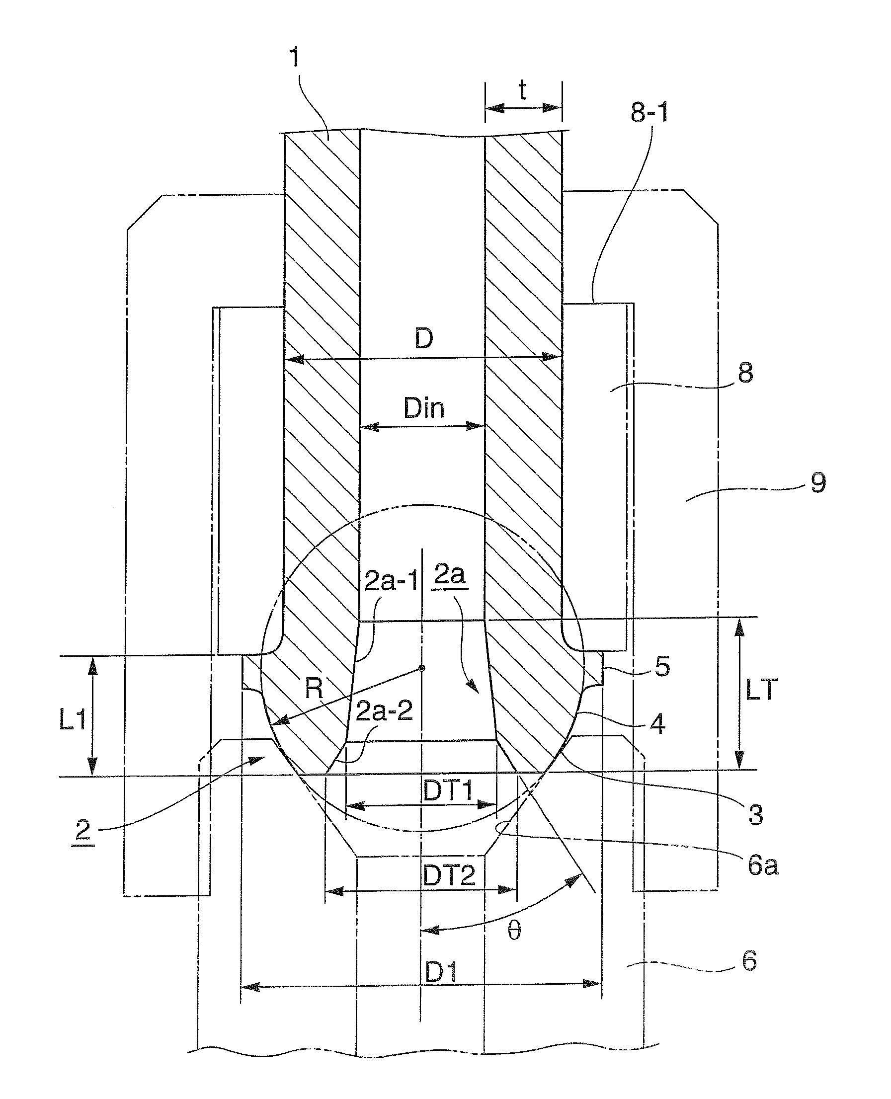
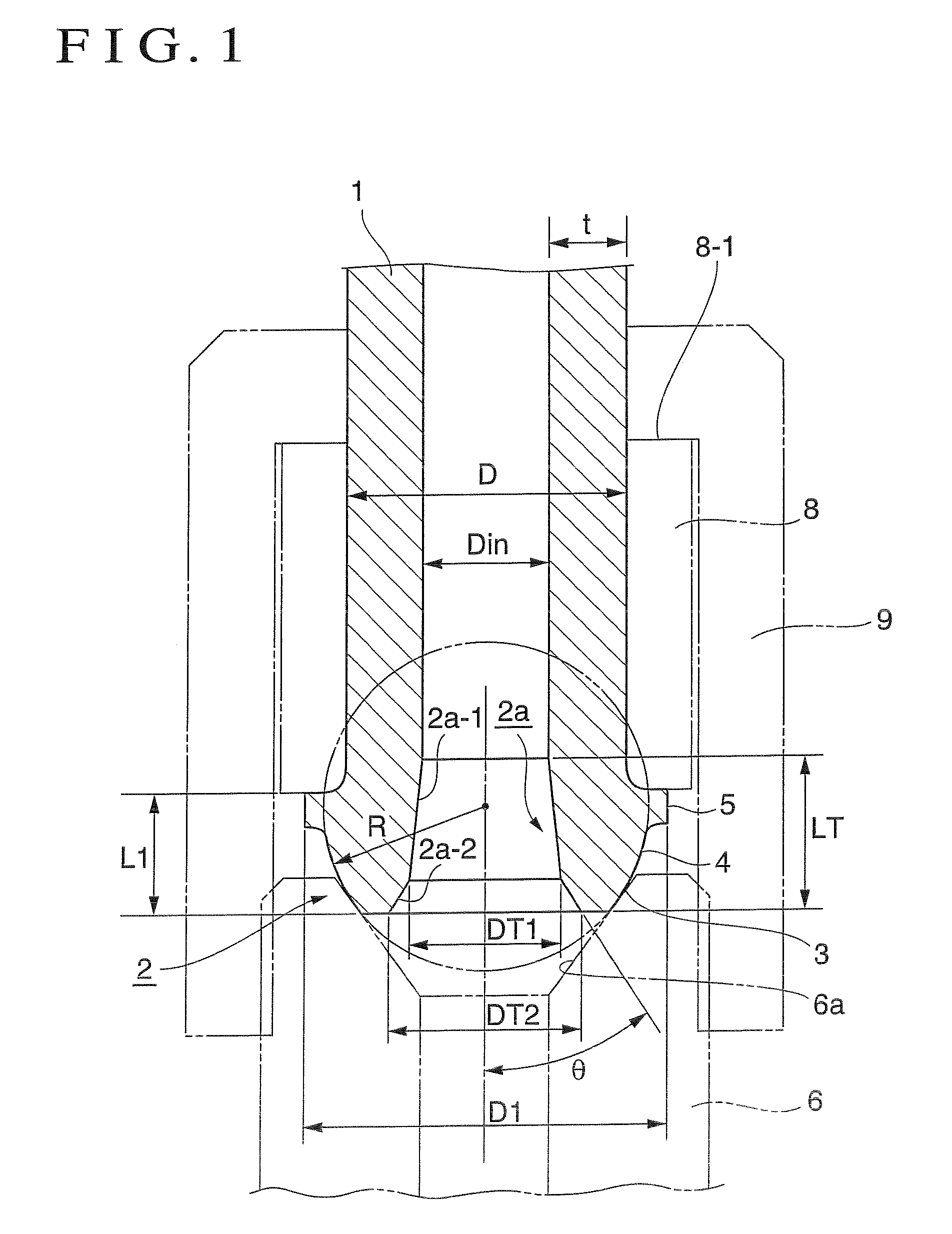
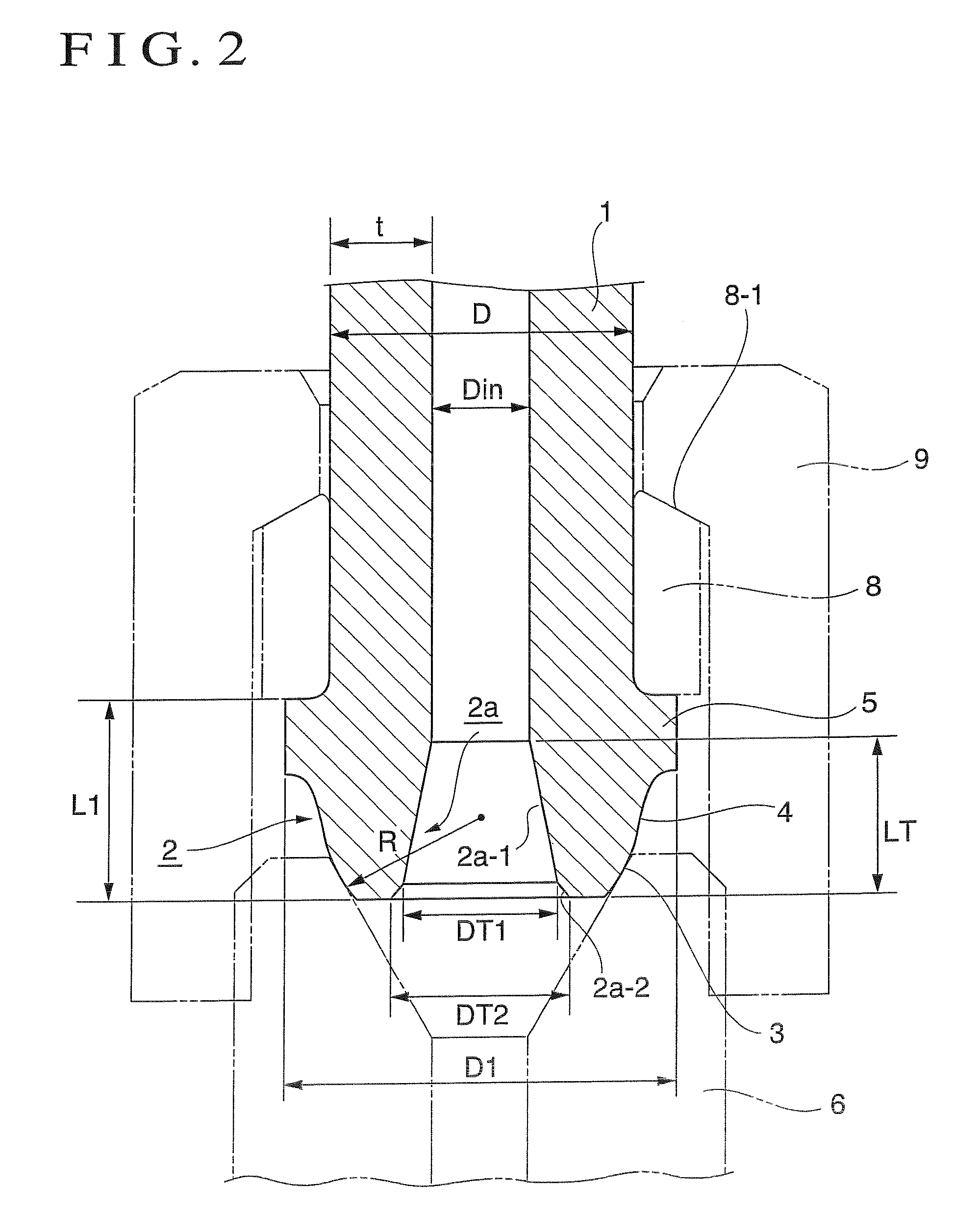
[0023]For a connection head structure of the present invention, and when a thick-walled thin-diameter steel tube has t (wall thickness) / D (outer diameter)1 from the connection head end to the back face of the annular flange is limited from 0.38 D to 0.7 D in order to ensure a tube axial direction length to avoid an interference between the annular flange and the opposing part; and because when the tube axial direction distance L1 is smaller than 0.38 D, the head cannot be formed; and on the other hand, when the tube axial direction distance L1 is larger than 0.7 D, a pocket is created and the pocket gradually becomes larger. Also, the spherical body radius R of the seat face is from 0.45 D to 0.65 D because when the spherical body radius R is smaller than 0.45 D, the head cannot be formed; and on the other hand, when the spherical body radius R is larger than 0.65 D, a pocket is created and the pocket gradually becomes larger. Further, the outer diameter D1 of the annular flange is ...


PUM


Abstract

A connection head structure of a high pressure fuel injection tube is provided to avoid an interference between an annular flange and an opposing part by sufficiently maintaining an tube axial direction length of the connection head and to obtain a good sealability to prevent leaking during autofrettage processing with a high pressure of not less than 300 MPa. A connection head structure of a high pressure fuel injection tube includes, on a connection end portion of a thick walled fine steel tube, a spherical seat face, an annular flange, and a circular conic face that continuously extends from the seat face, wherein a washer and a fastening nut are assembled, characterized in that when a thick walled fine steel tube has t (wall thickness) / D (outer diameter)<0.3, an tube axial direction distance L1 from a connection head end to the back face of the annular flange is from 0.38 D to 0.7 D, a spherical body radius R of the seat face is from 0.45 D to 0.65 D, and an outer diameter D1 of the annular flange is from 1.2 D to 1.4 D, wherein an inner circumferential face of the connection head includes a two stage tapered face having a cross section outline in a tube axial direction of the steel tube that broadens toward the aperture of the tube.

Description

BACKGROUND OF THE INVENTION[0001]1. Field of the Invention[0002]The present invention relates to a connection head structure of a high pressure fuel injection tube including a relatively thin-diameter thick-walled steel tube multifariously arranged as a supply path of fuel and the like for, as an example, a diesel internal combustion engine.[0003]2. Description of the Related Art[0004]Conventionally, as a high pressure fuel injection tube having such a connection head, as illustrated in FIG. 5, it is known to comprise a connection head 112 defined, on a connection end portion of a relatively thin-diameter thick-walled steel tube 111, by a spherical seat face 113, an annular flange 115 provided at an interval from the seat face 113 in a tube axial direction, and an arcuate face 114 that tapers toward a tip and continuously extends from the seat face 113 to the annular flange 115 (refer to FIG. 4 of Japanese Published Unexamined Patent Application No. 2003-336560). Such a connection h...

Claims


Application Information

Patent Timeline
Patent Type & Authority Patents(United States)
IPC IPC(8): F02M55/02
CPCF02M55/005F16L19/0286F02M55/02F02M2200/80F16L19/06
Inventor KATO, NOBUOHAYASHI, KOICHIUSUI, SHOICHIRO
Owner USUI KOKUSAI SANGYO KAISHA LTD
Why Eureka
Try Eureka