Apparatus for regulating flow of a medium in a heating and cooling system

a technology for regulating the flow of mediums in a heating and cooling system, which is applied in the direction of lighting and heating apparatus, instruments, heating types, etc., can solve the problems of limiting the available pressure difference across the flow limitation valve, affecting the function of the flow regulation valve, and affecting the flow of mediums

Inactive Publication Date: 2010-06-15
TOUR & ANDERSSON AB
View PDF21 Cites 24 Cited by
  • Summary
  • Abstract
  • Description
  • Claims
  • Application Information

AI Technical Summary

Benefits of technology

[0032]The desired maximal flow is guaranteed thanks to the fact, that the pressure difference part always provides a constant difference of the pressure Pd—Pr, maximal drop of pressure, which the flow regulating valve part 3 must than take care of. With this drop of pressure as a starting point it is then possible to choose the flow, which the valve is to provide by rotating rotary gate 34 in a stepless manner, the chosen opening degree corresponding to the desired flow. The rotary gate 34 cooperates with fixed cylindrical valve seat 32, which is mounted into top piece 13. On top piece 13 it is advantageous to attach a graduated collar 17, according to FIG. 2, which interacts with a pre-adjustment tool—not shown in the drawings—which is used, when a position for rotary gate 34 is to be chosen in relation to cylindrical valve seat 32. Pre-adjustment tool gears with holding case 45, which in its turn rotates rotary gate 34.

Problems solved by technology

The already known devices, designed to meet these objects, and in these cases primarily pressure difference regulators or flow regulation valves, are impaired by various drawbacks.
The limitation is caused by the fact, that, when a smaller flow is needed, a flow, which is smaller than the predicted one, to the valve, which is related to a definite pressure difference, must be added a valve, which eliminates this too large flow.
In this case this separate valve can be allowed to operate with a pressure level, which may cause noise, since the chosen pressure difference valve cannot check this smaller flow and thus not limit the pressure for this smaller flow.
One pressure difference valve and one flow regulating valve in order to obtain the desirable regulation functioning is of course an expensive solution.
A device, based on a flow regulation valve, can of course limit the flow, but such a system must include valves, which also limit the available pressure difference across the flow limitation valve.
In all these existing solutions the total cost is high, in case a satisfactory functioning in a set-up is to be achieved, partly because several units are required and partly because the existing pressure difference valves often are complicated constructions.
Since at least one pressure reducing function and one flow limiting function are required, in most set-ups, the final cost for the client will be high.
Two components must be installed and these often require some type of maintenance or control, which means elevated costs.

Method used


Image

  • Apparatus for regulating flow of a medium in a heating and cooling system
  • Apparatus for regulating flow of a medium in a heating and cooling system
  • Apparatus for regulating flow of a medium in a heating and cooling system

Examples


Embodiment Construction

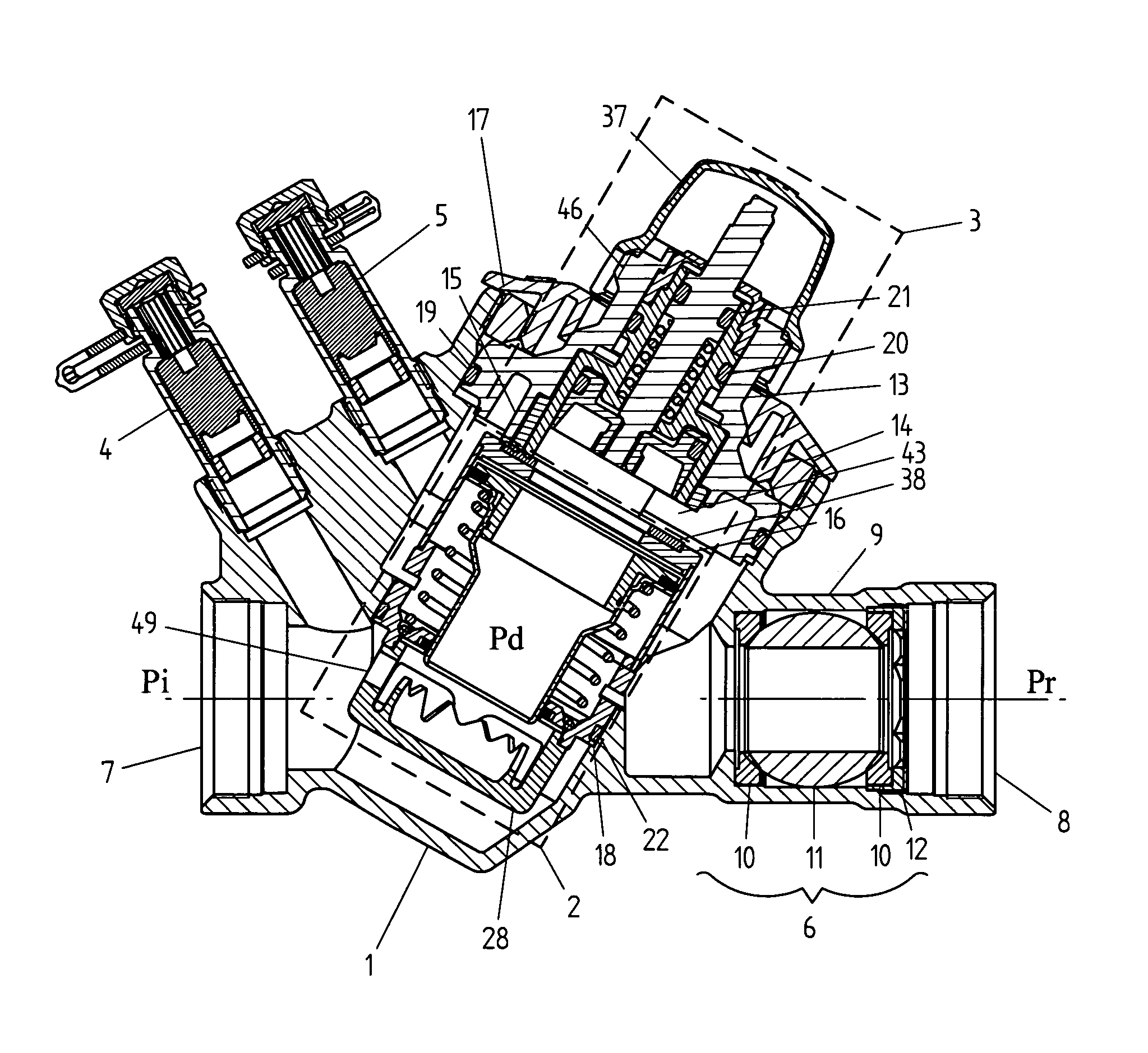
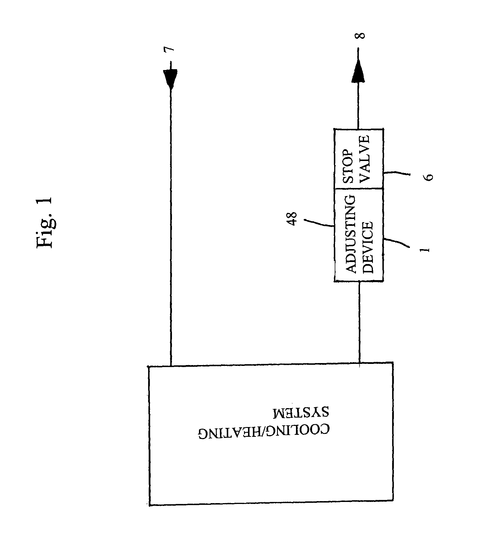
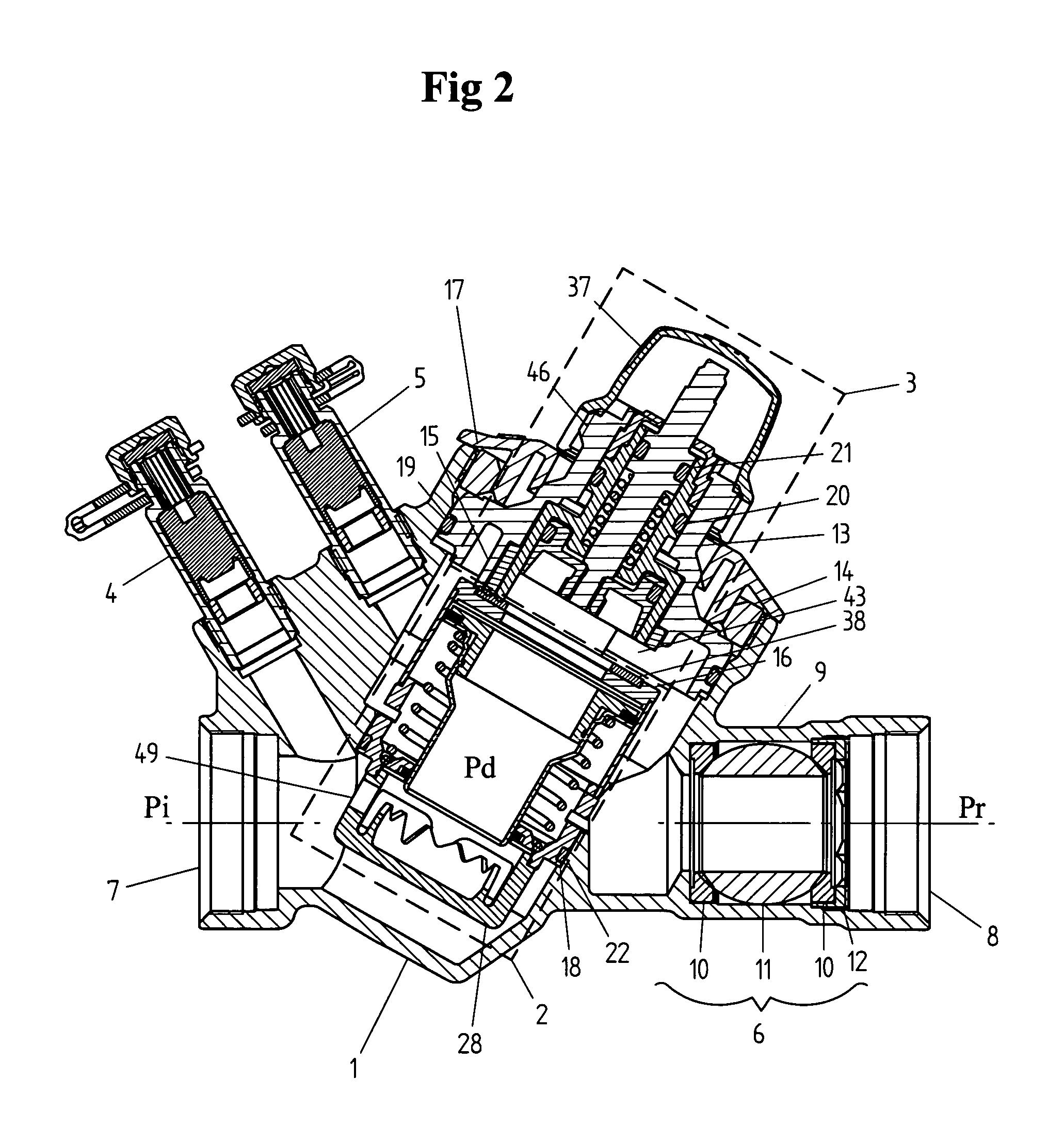
[0022]FIG. 2 shows the complete flow regulating valve 1, which comprises a connection 7 for the flow pipe and a connection 8 for the return flow pipe. The valve is provided with measuring outlets to be able to control the actual total drop of pressure across pressure difference part 2 and flow regulating valve part 3. In connection 4 the pressure in the flow pipe can be measured / registered as can the pressure in the return flow pipe in connection 5. The construction of the measuring nipples is known in the art. Examples regarding construction and operation are described in i.a. document SE 020 2851-2.

[0023]Also, the valve is provided with a stop valve 6, mounted in extended part 9 of return connection 8 of the valve. This stop valve can advantageously be a ball valve, in which is mounted with sealing elements 10 and a stop ball 11 and in which place these parts are fixed in an axial direction by means of a stop nut 12.

[0024]The regulating function of the complete valve consists of t...


PUM


Abstract

The description relates to a device for the regulation of the amount of a medium in a heating or cooling system, comprising a combined valve, which in one and the same valve housing includes one part for pressure difference regulation (2) and one part for flow limitation (3), the flow being limited in a stepless, adjustable way, i.e. the device obtaining an adjustable Kvs-value. Also, the chosen Kvs-value can be limited by a plunger, which always can operate with its complete stroke length.

Description

[0001]This application is a national stage completion of PCT / SE2005 / 001122 filed Jul. 7, 2005 which claims priority from Swedish Application Serial No. 0402206-7 filed Sep. 15, 2004.FIELD OF THE INVENTION[0002]The present invention relates to a device for the regulation of the amount of a flow, having an adjustable Kvs-value, in a heating and cooling system.BACKGROUND OF THE INVENTION[0003]The object of a device according to the present invention is to keep the flow constant by combining a pressure difference valve with an integrated check device. The check device can also be varied by choosing in a stepless manner a more or less open check device in order to in this way in the separate case let the desired flow reach a chosen pressure difference level.[0004]The already known devices, designed to meet these objects, and in these cases primarily pressure difference regulators or flow regulation valves, are impaired by various drawbacks.[0005]A device, based on a pressure difference r...

Claims


Application Information

Patent Timeline
Patent Type & Authority Patents(United States)
IPC IPC(8): G05D7/01F16KF16K11/22F16K17/04F24D19/10
CPCF16K1/526G05D7/0126F24D19/1015Y10T137/7788Y10T137/87137
Inventor MARSTORP, LEIFHOLMGREN, BJORN
Owner TOUR & ANDERSSON AB
Why Eureka
Try Eureka