Provisional bone plate

a bone plate and bone plate technology, applied in the field of bone plates, can solve the problems of increasing the cost of surgical procedures, increasing the cost of plate expense and surgical time, and utilizing trial and error procedures

Inactive Publication Date: 2010-06-15
ZIMMER INC
View PDF10 Cites 7 Cited by
  • Summary
  • Abstract
  • Description
  • Claims
  • Application Information

AI Technical Summary

Benefits of technology

[0018]A further advantage of the present invention is the fact that the provisional bone plate resists fracture when dropped.
is the fact that the provisional bone plate resists fracture when dropped.

Problems solved by technology

Having a plate that is longer than required to treat the fracture in question is more expensive in terms of both plate expense and surgical time.
Utilizing this trial and error procedure increases the costs of the surgical procedure because multiple bone plates must be purchased.

Method used


Image

  • Provisional bone plate
  • Provisional bone plate
  • Provisional bone plate

Examples


Embodiment Construction

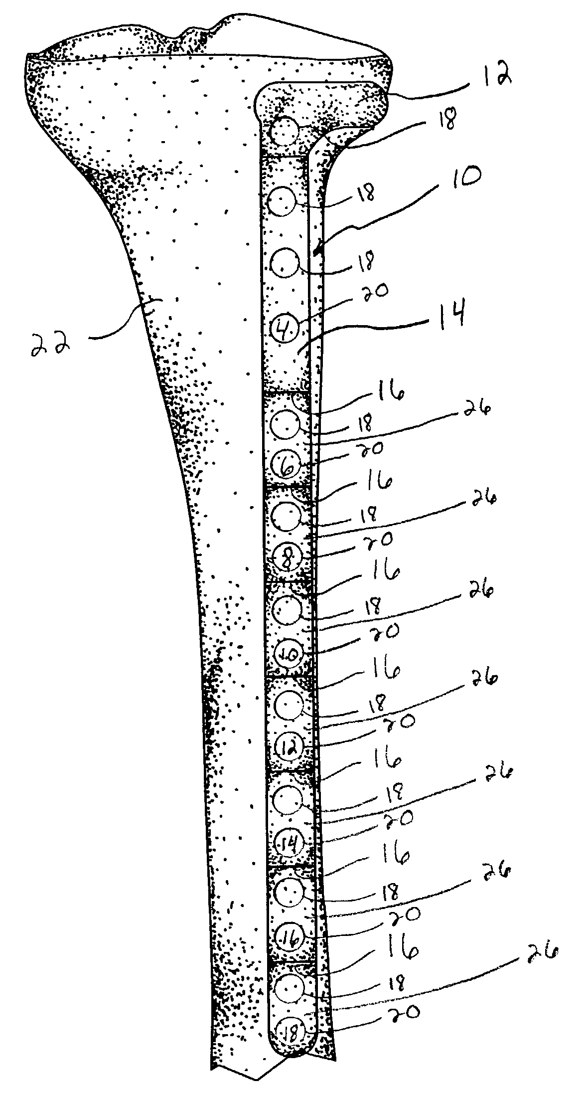
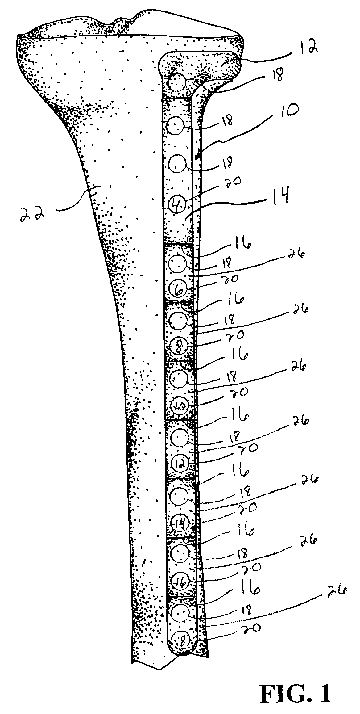
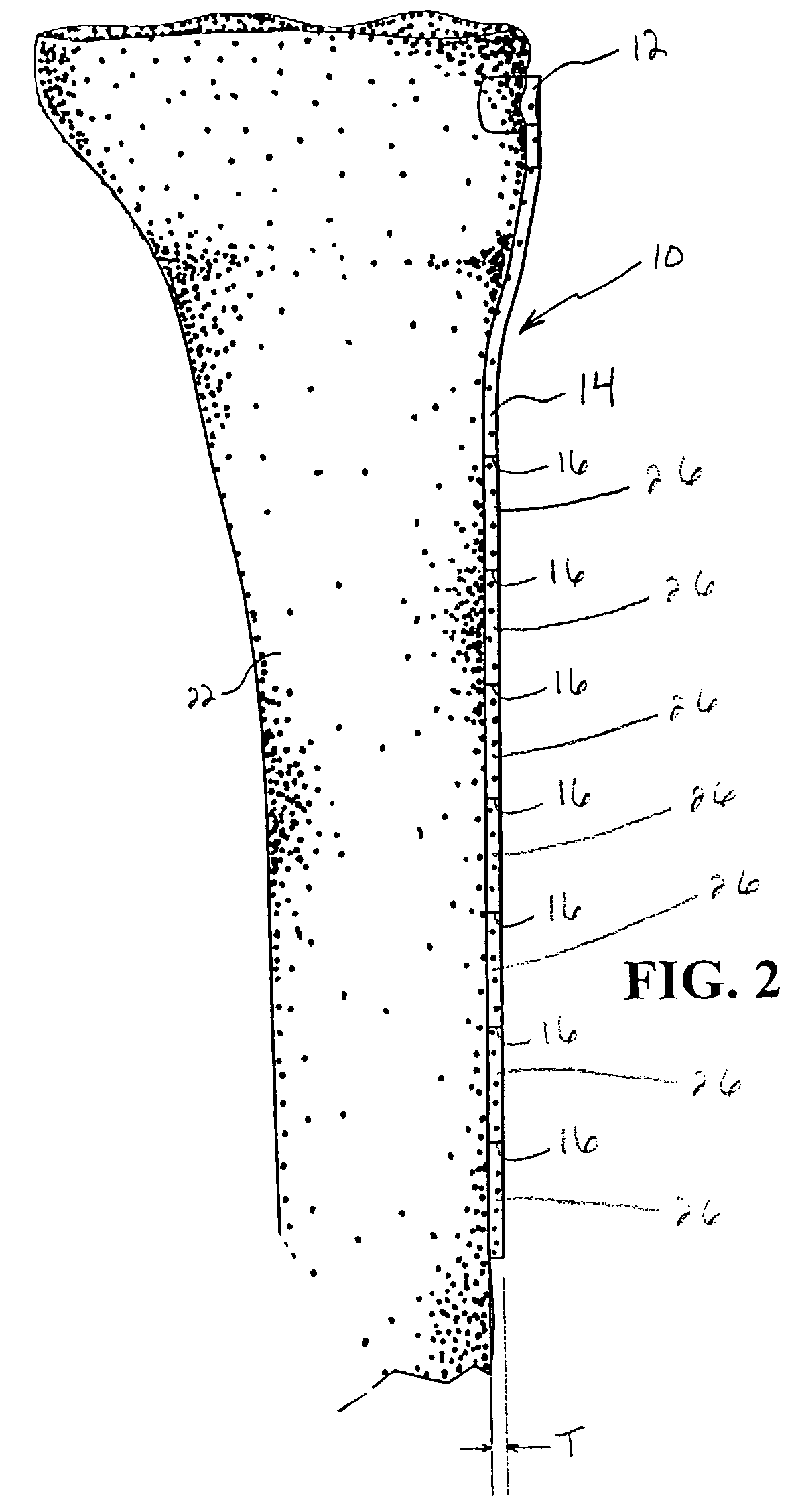
[0024]Referring to the drawings and particularly to FIG. 1, there is illustrated provisional bone plate 10 positioned adjacent tibia 22. As illustrated in FIG. 1, provisional bone plate 10 includes head 12 and elongate body or shaft 14. As illustrated in FIG. 1, head 12 is anatomically contoured to fit the head of tibia 22 similar to the contouring of the final bone plate. Provisional bone plate 10 includes a plurality of hole markings 18, 20, with holding markings 20 including a size indicator. Hole markings 18, 20 replicate the screw hole apertures found in the corresponding implantable bone plate. Hole markings 20 include size indicators useful in determining plate size as will be further described herein below.

[0025]As illustrated in FIGS. 1-3, provisional bone plate 10 includes a plurality of circumferential notches 16 defining a plurality of frangible portions 26. In one exemplary embodiment, circumferential notches 16 comprise V-shaped notches oriented substantially transvers...


PUM


Abstract

A provisional bone plate formed of an implantable plastic and having a length corresponding to the longest bone plate in a particular family of bone plates. The provisional bone plate includes a head contoured to match the head of a particular bone as well as a shaft for placement adjacent the bone shaft. The provisional bone plate includes a plurality of circumferential notches surrounding the elongate body or shaft of the bone plate. The circumferential notches are substantially transverse to a longitudinal axis of the bone plate and define frangible portions of the bone plate which can be removed from the distal end thereof to alter the length of the provisional periarticular bone plate to correspond to the length of the various bone plates in a family of bone plates. The provisional bone plate is constructed of a biologically suitable plastic, is radiographic, and melts at a temperature less than 200° Fahrenheit.

Description

BACKGROUND OF THE INVENTION[0001]1. Field of the Invention[0002]The present invention relates to bone plates, and, more particularly, to a provisional bone plate for determining the appropriately sized bone plate for a particular application.[0003]2. Description of the Related Art[0004]It is known to utilize bone plates in osteosynthesis. For example, the periarticular plating system available from Zimmer, Inc. is useful in osteosynthesis of periarticular bones. Known bone plates are used to maintain discrete portions of a fractured or otherwise severed bone substantially stationary relative to one another to, e.g., reduce a fracture and facilitate healing of the bone.[0005]Periarticular bones typically include a shaft with a head at either end. The heads of periarticular bones have an enlarged periphery relative to the periphery of the bone shaft to provide a larger load bearing surface at the bone end. Known bone plates attach to both the head and the shaft of the bone to maintain...

Claims


Application Information

Patent Timeline
Patent Type & Authority Patents(United States)
IPC IPC(8): A61F5/00A61B17/80A61B19/00
CPCA61B17/8061A61B2019/4873A61B2019/461A61B2019/307A61B2090/037A61B2090/061A61B2090/0814
Inventor PHILLIPS, MARKBRYANT, MARKDURCHOLZ, BRADLEY TMERCHANT, KRISHNAKANT K
Owner ZIMMER INC
Why Eureka
Try Eureka