Image forming apparatus for supplying toner from one of a plurality of toner cartridges

a technology of toner cartridges and forming apparatuses, which is applied in the direction of electrographic process apparatus, instruments, optics, etc., can solve the problems of difficult to detect the interruption of image forming actions, and the need for complicated procedures, etc., to achieve the effect of easy detection of the weight of toner in the toner cartridg

Inactive Publication Date: 2010-06-15
SHARP KK
View PDF8 Cites 5 Cited by
  • Summary
  • Abstract
  • Description
  • Claims
  • Application Information

AI Technical Summary

Benefits of technology

[0020]According to the invention, there is provided an image forming apparatus comprising: a plurality of toner cartridges for containing toners of an identical color; a toner supply section for supplying the toner from the toner cartridge to the developer container; a toner remaining amount detecting section for detecting individual remaining amounts of the toners contained in the toner cartridges; and a control section for controlling the toner supply section to select the toner cartridge having the least toner remaining amount detected by the toner remaining amount detecting section, and to supply the toner from the selected toner cartridge to the developer container. In this image forming apparatus, the toner can be preferentially supplied from the toner cartridge of the least toner remaining amount to the developer container. Therefore, when the toner cartridge before the end of use is employed, the toner cartridge before the end of use and to be earlier used can be preferentially employed. This makes it possible to prevent the toner cartridge before the end of use from being degraded in the charging characteristics and fluidity of the toner, as might otherwise be caused after left unused for a long time, so that an image of high quality can always be formed.
[0023]According to the invention, moreover, the toner remaining amount detecting section is disposed in each of the toner cartridges, and the toner remaining amount detecting section includes the nonvolatile memory in which the toner remaining amount detection information which is the information on the remaining amount of the toner contained in the toner cartridge, is stored. As a result, it is possible to easily grasp the toner remaining amount in the toner cartridge.
[0026]According to the invention, moreover, the toner remaining amount detecting section includes the first wireless transmitting / receiving section disposed in each of the toner cartridges for transmitting the toner remaining amount detection information stored in the nonvolatile memory, to the outside, and the control section includes the second wireless transmitting / receiving section for receiving the toner remaining amount detection information transmitted from the first wireless transmitting / receiving section, thereby to control the toner supply section in accordance with the toner remaining amount detection information obtained by the second wireless transmitting / receiving section. As a result, the toner remaining amount detecting section and the control section can communicate in a non-contact manner so that the arrangement of the toner remaining amount detecting section and the control section can be freely set to spare the space for the apparatus.
[0028]According to the invention, moreover, the toner supply section is a rotational drive section which is disposed in each of the toner cartridges, for rotating the toner cartridge to supply the toner. The supply of the toner by the rotation of the toner cartridge is performed, for example, by rotating the toner cartridge of a substantially cylindrical shape about an axis thereof so that the toner may be guided to and fed out from an opening formed in the toner cartridge. This toner supply can make constant the quantity of toner to be fed by the rotation to the opening so that the supply amount of the toner can be stabilized to a predetermined value. Moreover, the toner can be prevented from sticking to the inner wall of the toner cartridge by the rotation of the toner cartridge and accordingly from being left in the toner cartridge. Moreover, it is unnecessary to provide the toner cartridge with a complicated agitating section for preventing the toner from agglomerating in the toner cartridge.
[0031]According to the invention, moreover, the toner cartridge includes the rotation number detecting unit for detecting the number of rotations of the toner cartridge, wherein the accumulated value of the number of rotations of the toner cartridge which number of rotations is detected by the rotation number detecting unit, is stored as the toner remaining amount detection information in the nonvolatile memory. As a result, the weight of the toner contained in the toner cartridge can be easily detected without providing a weight sensor for detecting the toner weight in the toner cartridge.
[0034]According to the invention, moreover, the toner cartridge includes the rotation number detecting unit for detecting the number of rotations of the toner cartridge, and the remaining amount calculating section for calculating the remaining amount of the toner reserved in the toner cartridge, from the accumulated value of the number of rotations of the toner cartridge which number of rotations is detected by the rotation number detecting unit, wherein the toner remaining amount calculated by the remaining amount calculating section is stored as the toner remaining amount detection information in the nonvolatile memory. As a result, the weight of the toner in the toner cartridge can be easily detected without any weight sensor.

Problems solved by technology

At the time of replacing the toner cartridges, however, it is impossible to avoid the interruption of the image forming actions.
In order to employ the toner cartridge before the end to be earlier employed, therefore, the complicated procedure is required for exchanging the unused toner cartridge to be mounted on the other mounting portion and the toner cartridge before the end of use.
During this replacing procedure, moreover, there occurs a time period, for which none of the toner cartridges is mounted, to raise a problem that the image forming actions are interrupted.

Method used


Image

  • Image forming apparatus for supplying toner from one of a plurality of toner cartridges
  • Image forming apparatus for supplying toner from one of a plurality of toner cartridges
  • Image forming apparatus for supplying toner from one of a plurality of toner cartridges

Examples


Embodiment Construction

[0042]Now referring to the drawings, preferred embodiments of the invention are described below.

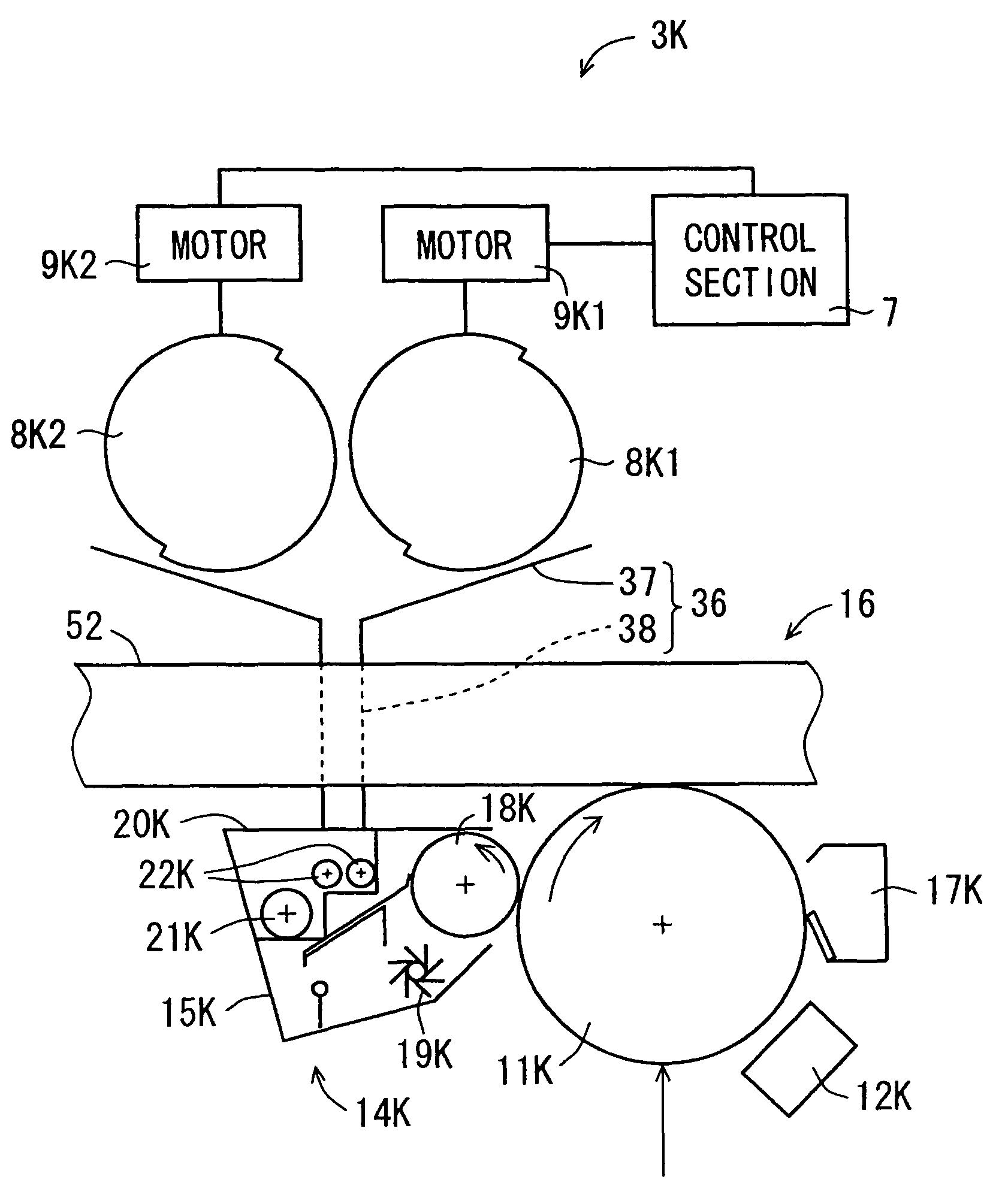
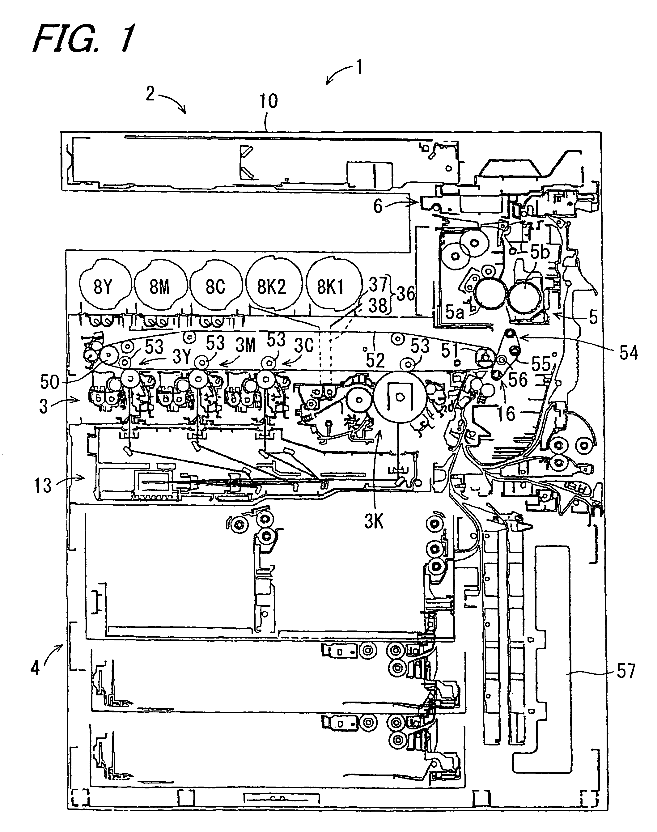
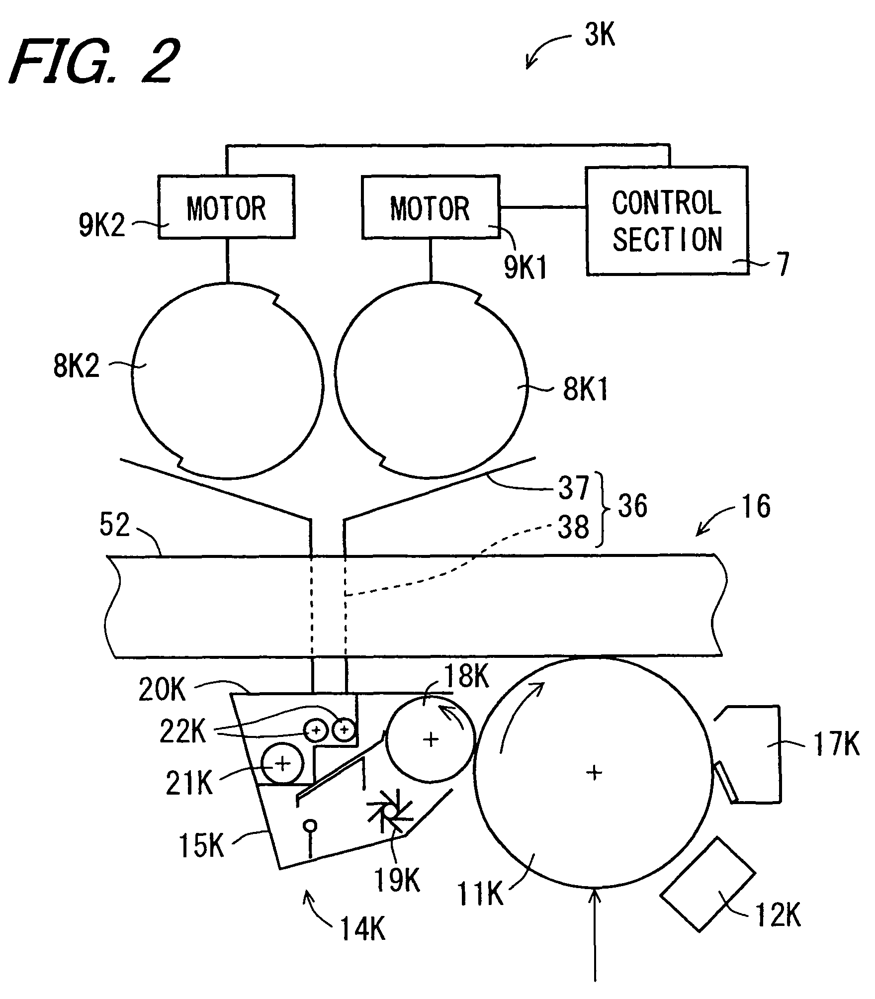
[0043]FIG. 1 is a diagram showing a constitution of an image forming apparatus 1 according to one embodiment of the invention, and FIG. 2 is an enlarged diagram schematically showing a constitution around a developing section 14K, as belonging to the image forming apparatus 1 shown in FIG. 1, of a black image. The image forming apparatus 1 is a full-color image forming apparatus using the electronic photography, as exemplified a multifunctional system having the functions of a copier, a printer and the like.

[0044]The image forming apparatus 1 is constituted to include an image information reading unit 2, an image processing unit (not shown), an image forming unit 3, a paper feeding unit 4, a fixing unit 5, a paper discharge unit 6 and a control section 7. The image information reading unit 2 reads image information of a document. The image processing unit image processes either the image ...


PUM


Abstract

An image forming apparatus capable of selecting a toner cartridge from a plurality of toner cartridges containing toner of an identical color preferentially without interrupting an image forming action of the apparatus. When a toner density of the toner in a developer container becomes low, a control section drives a toner supply section in response to information on the remaining amount of the toner contained in the toner cartridges, so that the toner may be supplied from the toner cartridge having the least remaining amount.

Description

BACKGROUND OF THE INVENTION[0001]1. Field of the Invention[0002]The present invention relates to an image forming apparatus.[0003]2. Description of the Related Art[0004]An image forming apparatus using the electronic photography is generally constituted to include a photoreceptor which is a rotating image bearing member, and a charging section, an exposure section, a developing section, a transfer section, a fixing section, a cleaning section and a deelectrification section, which are arranged around the photoreceptor. The charging section charges the surface of the photoreceptor uniformly. The exposure section exposes the photoreceptor surface charged, to light according to image information thereby to form an electrostatic latent image. The developing section agitates and charges the toner so that a toner image is formed by adhering the frictionally charged toner to the electrostatic latent image formed on the photoreceptor surface. The transfer section transfers the toner image t...

Claims


Application Information

Patent Timeline
Patent Type & Authority Patents(United States)
IPC IPC(8): G03G15/08
CPCG03G2215/0695G03G2215/0697G03G2215/0888G03G15/0856G03G15/0858G03G15/0872
Inventor SAKITA, HIROFUMINISHIMURA, HIDEYUKIKOBAYASHI, HISAAKIIZUMI, HIROKAZU
Owner SHARP KK
Why Eureka
Try Eureka