Winch bar with offset handle

a technology of offset handle and winch bar, which is applied in the field of winch bars, can solve the problems of user's upper body or face falling towards the ground, serious physical injury, and user's upper body or face falling, so as to reduce the tendency of the winch bar and reduce the slope of the handle

Active Publication Date: 2010-06-22
THE WESTBERG GROUP
View PDF31 Cites 1 Cited by
  • Summary
  • Abstract
  • Description
  • Claims
  • Application Information

AI Technical Summary

Benefits of technology

[0035]As another feature, one or more compensating angles may place a portion of the handle of a winch bar parallel with the central axis of the spool drive engagement portion, reducing the tendency of the winch bar to rotate down in response to force applied to the winch bar to turn the winch spool, and providing a handle alignment that helps reduce the slope of the handle.

Problems solved by technology

This often causes the winch bar user to fall towards the ground, potentially hitting his or her upper body or face against the trailer, the winch bar, a fender of the trailer, or even the ground.
The user could thus sustain serious physical injury.
Such slipping out may cause the winch bar user to fall towards the ground, potentially striking various portions of himself or herself against the winch bar, trailer, etc., with a possibility of substantial injury.
Another considerable risk in use of a conventional winch bar 38 is the downward slope of the handle portion 42 when the winch bar 38 is used in the most commonly used position, angled down.
This has a tendency of causing the user's grip to slip along the handle portion 42, causing the user to fall towards the winch bar, trailer, and ground, thereby often sustaining injury.
A number of prior winch bars or winch bar-like devices have not adequately addressed the above-described risks.

Method used


Image

  • Winch bar with offset handle
  • Winch bar with offset handle
  • Winch bar with offset handle

Examples


Embodiment Construction

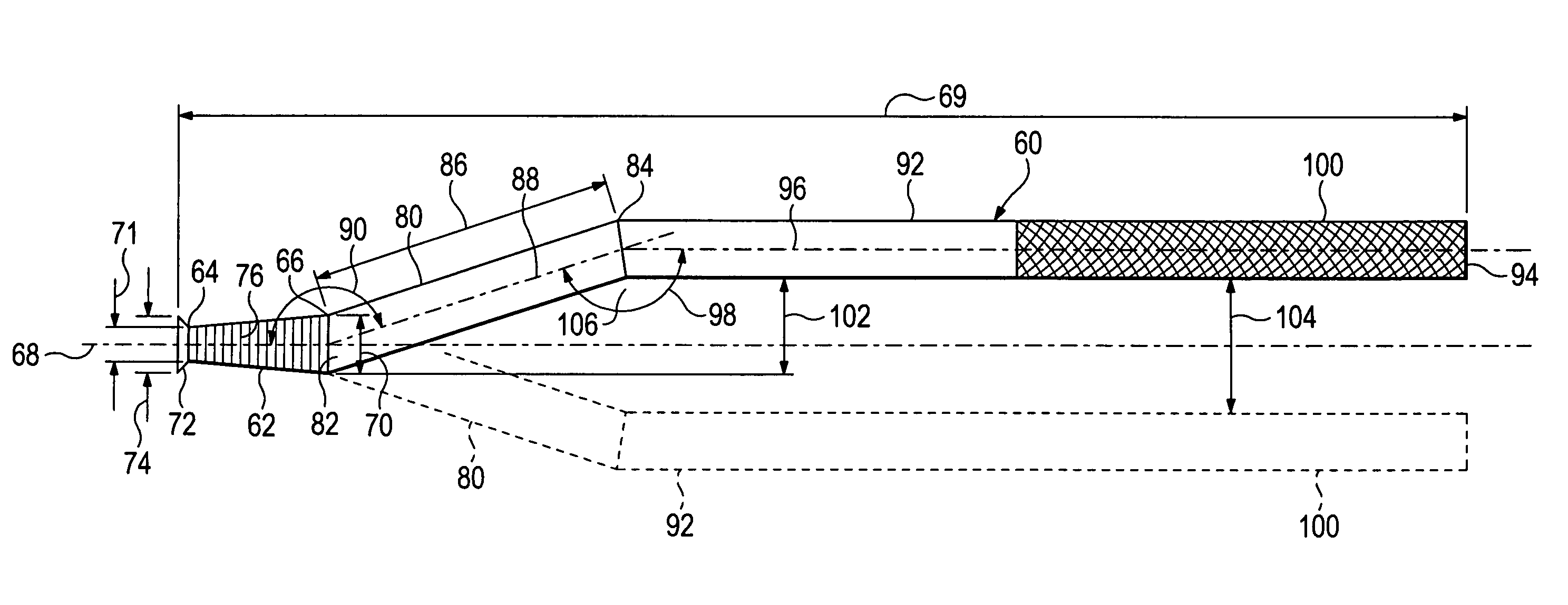
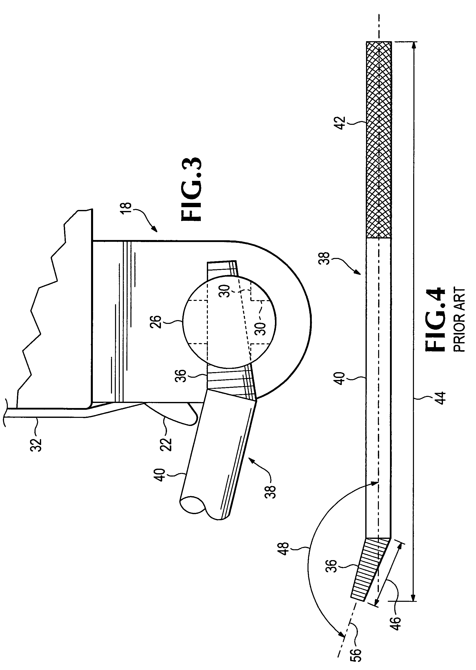
[0054]Referring again to the drawings which form a part of the disclosure herein, a winch bar 60 shown in FIG. 7 includes a winch drive engagement portion 62 that has a tip 64 and a root end 66 and defines a central longitudinal axis 68. The overall length 69 of the winch bar 60 may be similar to that of the previously known winch bars such as the winch bar 38 shown in FIG. 4, such as 31 to 40 inches, for example, although a length 69 in the range of 24-48 inches could also be useful, and a length 69 of 36 inches might be convenient in view of a common toolbox size. The drive engagement portion 62 may be conical, tapered from a slightly larger diameter 70 at the root end 66 toward a smaller diameter 71 near the tip 64, and may be circular in cross section as viewed along the central longitudinal axis 68. At the tip 64 a safety catch 72 extends radially to a larger diameter 74 which may be similar to or slightly smaller than the diameter 70 at the root end. The safety catch 72 may ex...


PUM

PropertyMeasurementUnit
lateral offset distanceaaaaaaaaaa
lengthaaaaaaaaaa
lengthaaaaaaaaaa

Abstract

A winch bar for use together with a strap winch to tighten a load-securing strap for a flatbed truck or trailer. In addition to an offset angle, the winch bar also includes one or more compensating angles establishing an obstacle clearance area defined by a laterally offset portion of the winch bar.

Description

CROSS-REFERENCE TO RELATED APPLICATIONS[0001]This is a continuation-in-part of U.S. patent application Ser. No. 12 / 070,296, filed Feb. 14, 2008.BACKGROUND OF THE INVENTION[0002]The present invention relates to winch bars. More particularly, the present invention relates to winch bars for strap winches such as are used on flatbed trailers.[0003]Flatbed trailers of various lengths, widths, and load capacities are used to transport materials of various types from one location to another, both on and off roadways.[0004]Loads are usually secured to such flatbed trailers by one or more straps of woven webbing extending over a load from one side of the trailer to the other side. Each strap is tightened by being wound on a strap winch such as the strap winch 18 shown in FIGS. 1-3, mounted at one side of the trailer. Such a strap winch usually includes a ratchet mechanism including a ratchet wheel 20 and a related pawl 22 on a spool 24, and a spool drive hub, or winch bar receiver 26, so tha...

Claims


Application Information

Patent Timeline
Patent Type & Authority Patents(United States)
IPC IPC(8): B25B25/00
CPCB60P7/0853Y10T74/20744Y10T16/469Y10T74/20738Y10T16/498
Inventor WESTBERG, STEVEN A.
Owner THE WESTBERG GROUP
Why Eureka
Try Eureka