Landing gear having a gas vessel, and methods of maintaining such landing gear

a technology of landing gear and gas vessel, which is applied in the direction of mechanical equipment, shock absorbers, transportation and packaging, etc., can solve the problems of affecting the scheduling of the line provided, running the risk of injuring passengers or damaging fuel tanks,

Active Publication Date: 2005-09-29
SAFRAN LANDING SYSTEMS
View PDF10 Cites 11 Cited by
  • Summary
  • Abstract
  • Description
  • Claims
  • Application Information

AI Technical Summary

Benefits of technology

[0009] Thus, when the shutter member opens, the first chamber has its volume increased by the volume of the vessel, thereby reducing the slope of the curve plotting force generated in the shock absorber while it is being shortened. Reducing the slope of the force curve provides a corresponding reduction in the maximum force generated by the shock absorber, thereby limiting said force. The integrity of the landing gear is thus saved.
[0011] The stability of the open position makes it easy to detect that the safety mechanism of the invention has been triggered by measuring the pressure in the first chamber which, for a given amount of shock absorber shortening, differs depending on whether or not the shutter member is closed or open, or in a variant by measuring the extent to which the shock absorber has shortened, which for given pressure in the first chamber differs depending on whether the shutter member is closed or open.

Problems solved by technology

For landing gear situated under the fuselage of the airplane, it is important to ensure that the landing gear cannot break free from its attachment points, since that would run the risk of injuring passengers or of damaging fuel tanks.
However, such systems are difficult to design and they require any buckled structural portions to be replaced before the airplane can take off again, and that can disturb the scheduling of the line provided by the airplane and can be problematic when the airplane is to be found at an airport that is remote and isolated.

Method used


Image

  • Landing gear having a gas vessel, and methods of maintaining such landing gear
  • Landing gear having a gas vessel, and methods of maintaining such landing gear

Examples


Embodiment Construction

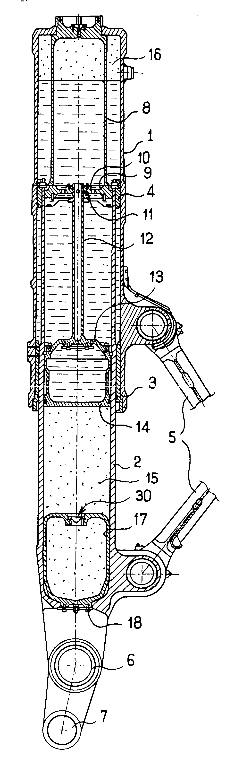
[0021] The invention is applied herein to landing gear of the direct type with an integrated shock absorber mounted beneath the fuselage of an airplane. Clearly the invention is not restricted to this type of landing gear, and is also applicable to landing gear having an external shock absorber, and not necessarily mounted under the fuselage.

[0022] With reference to FIG. 1, and in conventional manner, the landing gear comprises a strut 1 connected to the airplane, having a rod 2 mounted to slide therein in sealed manner. To this end, the strut 1 carries at its bottom end a bottom bearing 3 having an inside surface in contact with the rod 2, and the rod 2 carries at its top portion a top bearing 4 having an outside surface in contact with the strut 1.

[0023] A scissors linkage 5 (of which only the ends of the branches can be seen) is mounted between the strut 1 and the rod 2 to prevent the rod 2 from turning relative to the strut 1.

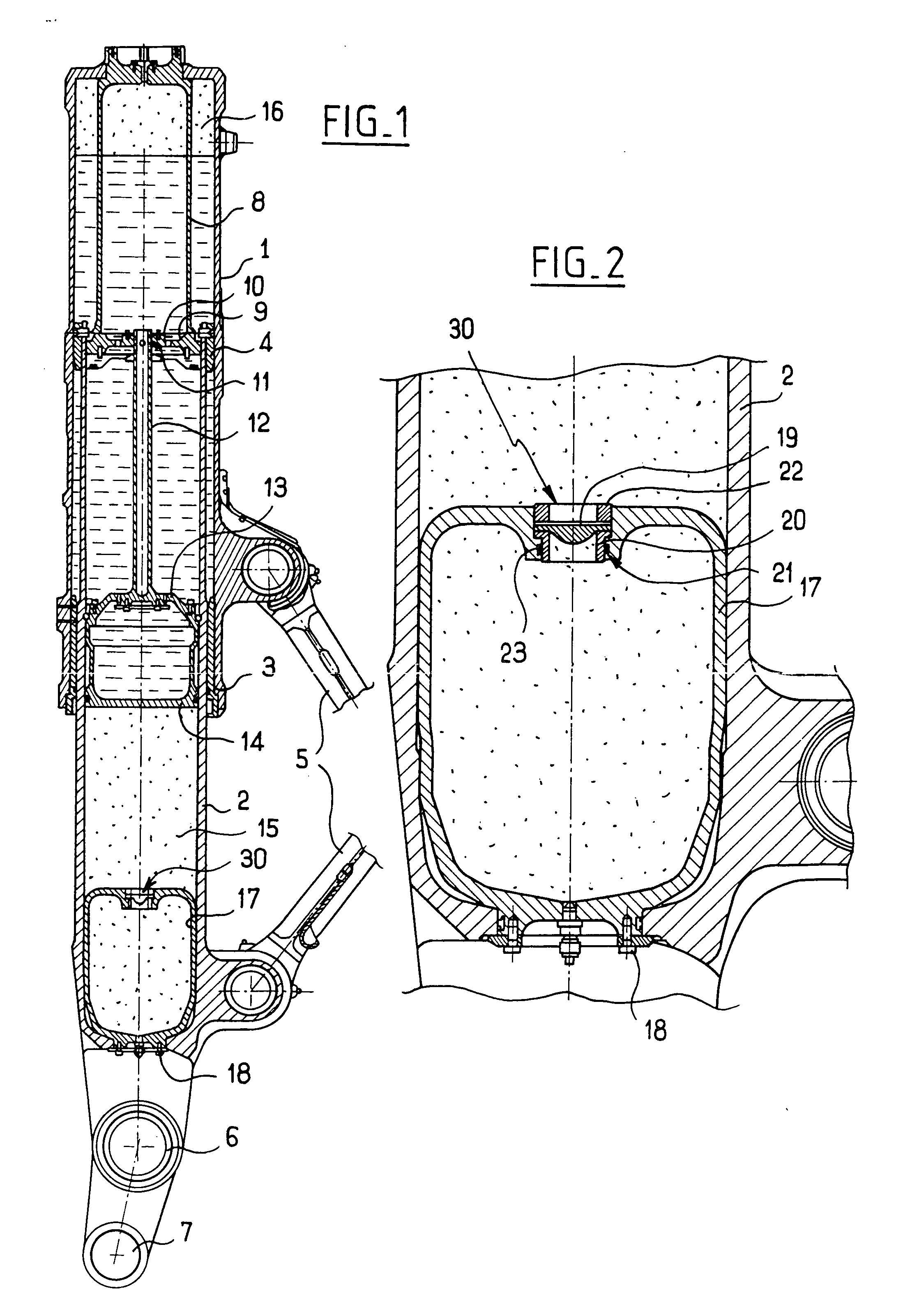
[0024] At its bottom end, the rod 2 forms a fork w...


PUM


Abstract

A landing gear includes a shock absorber having first and second elements slidable relative to each other, the slidable elements defining an inside volume which is filled in part with hydraulic fluid so as to leave a first chamber filled with gas under pressure and located at the end of one of the slidable elements. A vessel filled with gas under pressure is housed in the end and is provided with a shutter member that is initially in a closed state and that is suitable for taking up a stable open state when the pressure in the first chamber exceeds the pressure in the vessel by a predetermined threshold amount.

Description

[0001] The invention relates to landing gear having a gas vessel, and to a method of maintaining such landing gear. BACKGROUND OF THE INVENTION [0002] Landing gear is known that includes a shock absorber having a first element and a second element that are mounted to be slidable relative to each other, said slidable elements defining an internal volume which is filled in part with hydraulic fluid so as to leave a chamber filled with gas under pressure at the end of one of the slidable elements. [0003] In general, one of the elements of the shock absorber includes a diaphragm that presents throttling orifices through which the hydraulic fluid is forced when the shock absorber is shortened. This throttling dissipates a fraction of the kinetic energy of the airplane that has led to the shock absorber being shortened. [0004] Another fraction of the kinetic energy is absorbed by compressing the gas contained in the chamber, by reducing the volume of said chamber as the shock absorber sho...

Claims


Application Information

Patent Timeline
Patent Type & Authority Applications(United States)
IPC IPC(8): B64C25/60F16F9/06
CPCF16F9/064B64C25/60
Inventor COURTOIS, MAUDGAUTRAIN, SEBASTIENGILLET, MARCMARTINEZ, LAURENT
Owner SAFRAN LANDING SYSTEMS
Why Eureka
Try Eureka