Plasma display panel and driving method thereof

a technology of display panel and drive method, which is applied in the direction of identification means, instruments, computing, etc., can solve the problems of not actively processing the variation in the reset period, no stable reset operation, and requiring resistors for current restriction, so as to prevent misfiring and increase the rise time, the slope of the rising waveform may decrease, and the effect of preventing misfiring

Inactive Publication Date: 2005-07-21
SAMSUNG SDI CO LTD
View PDF2 Cites 12 Cited by
  • Summary
  • Abstract
  • Description
  • Claims
  • Application Information

AI Technical Summary

Benefits of technology

[0019] One advantage of the present invention may be to provide a device and method for driving a PDP for generating a reset waveform for preventing misfiring and realizing high-speed addressing.
[0020] The invention relates to a device in a PDP that displays light with varying intensities. In such a system it may be valuable to perform some intelligent reset operations rather than to apply the same result pulse in every subfield without regard to the non-ideal discharge cells in a PDP.
[0021] Accordingly, it may be appropriate to determine the number of cells that are in an ON state in each subfield. Based on some a priori information regarding the size and layout of the PDP, one may then determine whether the number of ON cells is enough to surpass a threshold.
[0022] If the number of ON cells surpasses the threshold, a number of modifications to the reset pulse may be made. The starting voltage of the rising waveform, for example, may decrease. Another modification that may be made is that the slope of the rising waveform may decrease (i.e. the rise time may increase). Yet another modification is that the fall time of the falling waveform may increase.
[0023] A threshold can also be used negatively, to trigger changes to the reset pulse when the number of ON cells does not exceed the threshold. It is even possible to include multiple thresholds and to modify the waveform of the reset pulse based on which thresholds have been (or not been) surpassed. In the extreme example, each marginal ON cell triggers a slight modification to the reset pulse.
[0024] In another embodiment, the relevant number of ON cells may be the number of cells within a segment of the PDP. This may be a particularly useful approach in especially large PDPs. The segment may correspond to physical boundaries of a manufactured component, or it may correspond to a group of cells located most proximate to the relevant cell. In a further embodiment of the present invention, the ON state of cells closest to the relevant cell would be weighted higher than those more distally located.

Problems solved by technology

Because DC PDPs have electrodes exposed in the discharge space, they allow electric current to flow in the discharge space while the voltage is supplied, and they therefore problematically require resistors for current restriction.
As a result, the load variation in the reset period is not actively processed, and no stable reset operation is performed.

Method used


Image

  • Plasma display panel and driving method thereof
  • Plasma display panel and driving method thereof
  • Plasma display panel and driving method thereof

Examples


first embodiment

[0054] The start voltage of the rising ramp pulse may be controlled while the gradient of the rising ramp pulse may be maintained constantly in the first embodiment, and the gradient of the rising ramp pulse can also be modified.

[0055]FIGS. 6A and 6B show Y electrode driving waveform diagrams of a PDP according to a second exemplary embodiment of the present invention.

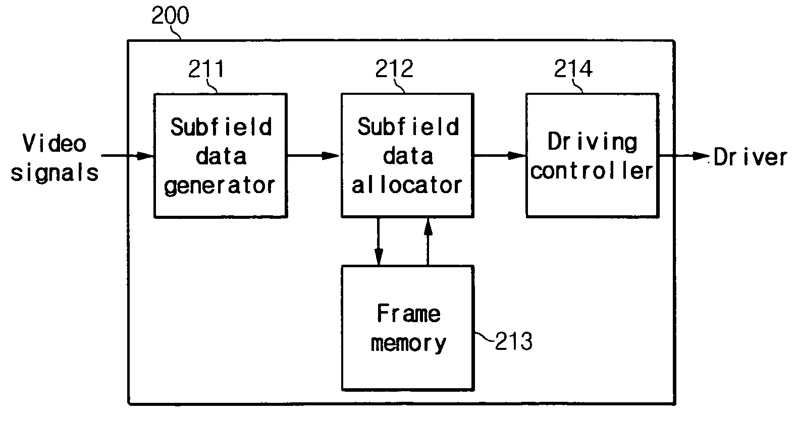
[0056] Because the subfield after the subfield with a high weight has a low discharge firing voltage, a strong discharge may be generated during the reset period. Hence, the driving controller 214 may allow the gradient of the rising ramp pulse to be less than the gradient of the rising ramp pulse applied during the reset period of the first subfield, and may gradually increase the voltage to prevent generation of a strong discharge as shown in FIG. 6A. Consequently, the time t3 for applying the rising ramp pulse will be longer than the time tr for applying the rising ramp pulse in the first subfield, under these cond...

fourth embodiment

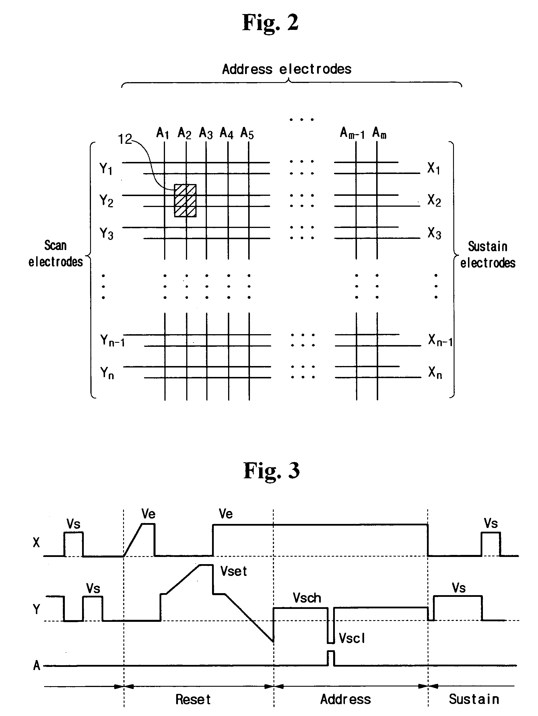
[0062] As shown in FIGS. 8A and 8B, while the voltage at the X electrode is fixed to be Ve during the reset period the voltage applied to the Y electrode may be reduced by a predetermined amount. Meanwhile the voltage supplied to the Y electrode during the period of Tf may be intercepted to float the Y electrode. The operation of reducing the voltage at the Y electrode by a predetermined amount and floating the Y electrode for a predetermined time Tf may be repeated.

[0063] When the voltage difference between the voltage of Vx at the X electrode and the voltage of Vy at the Y electrode becomes greater than the discharge firing voltage Vf while the operation is being repeated, a discharge may occur between the X and Y electrodes. That is, a discharge current Id flows in the discharge space. When the Y electrode is floated after the start of a discharge between the X and Y electrodes, the voltage at the Y electrode may be varied according to the amount of the wall charges. This is bec...


PUM


Abstract

Disclosed is a PDP driving method which may include generating subfield information that shows ON / OFF states of discharge cells from among a plurality of subfields from input image signals, generating address information that shows ON / OFF states of the discharge cells per subfield from the subfield data, counting the number of the discharge cells that are ON from among the discharge cells from the address data, and controlling a waveform applied during a reset period of a subsequent subfield.

Description

CROSS REFERENCE TO RELATED APPLICATION [0001] This application claims priority to and the benefit of Korea Patent Application No. 2003-75946 filed on Oct. 29, 2003, in the Korean Intellectual Property Office, the entirety of which is hereby incorporated by reference. BACKGROUND OF THE INVENTION [0002] 1. Field of the Invention [0003] The present invention relates to a PDP (plasma display panel) driving method. More specifically, the present invention relates to a PDP driving method for reducing a reset time. [0004] 2. Description of the Related Art [0005] Recently, LCDs (liquid crystal displays), FEDs (field emission displays), and PDPs have been actively developed. PDPs have better luminance and light emission efficiency compared to the other types of flat panel devices, and also have wider view angles. Therefore, PDPs have come into the spotlight as substitutes for conventional CRTs (cathode ray tubes) in large displays of greater than 40 inches. [0006] A PDP is a flat display tha...

Claims


Application Information

Patent Timeline
Patent Type & Authority Applications(United States)
IPC IPC(8): G09G3/28G09F9/313G09G3/288H01J17/49
CPCG09G3/2927G09G3/296
Inventor KANG, KYOUNG-HOCHUNG, WOO-JOONKIM, JIN-SUNGCHAE, SEUNG-HUNKIM, TAE-SEONG
Owner SAMSUNG SDI CO LTD
Why Eureka
Try Eureka