Undercarriage with a three-chamber shock absorber

Inactive Publication Date: 2005-10-20
MESSIER DOWTY
View PDF12 Cites 9 Cited by
  • Summary
  • Abstract
  • Description
  • Claims
  • Application Information

AI Technical Summary

Benefits of technology

[0006] An object of the invention is to provide a shock absorber provided with a safety device enabling the force transmitted by the shock absorber to be limited, and not requiring an immediate maintenance operation after the safety device has been triggered.

Problems solved by technology

However such systems are difficult to design, and they require any buckled structural portions to be replaced before it is possible for the airplane to take off again, and that can interfere with regular service on the line provided by the airplane and can be awkward when the airplane is located at an airport that is remote and isolated.

Method used


Image

  • Undercarriage with a three-chamber shock absorber
  • Undercarriage with a three-chamber shock absorber

Examples


Embodiment Construction

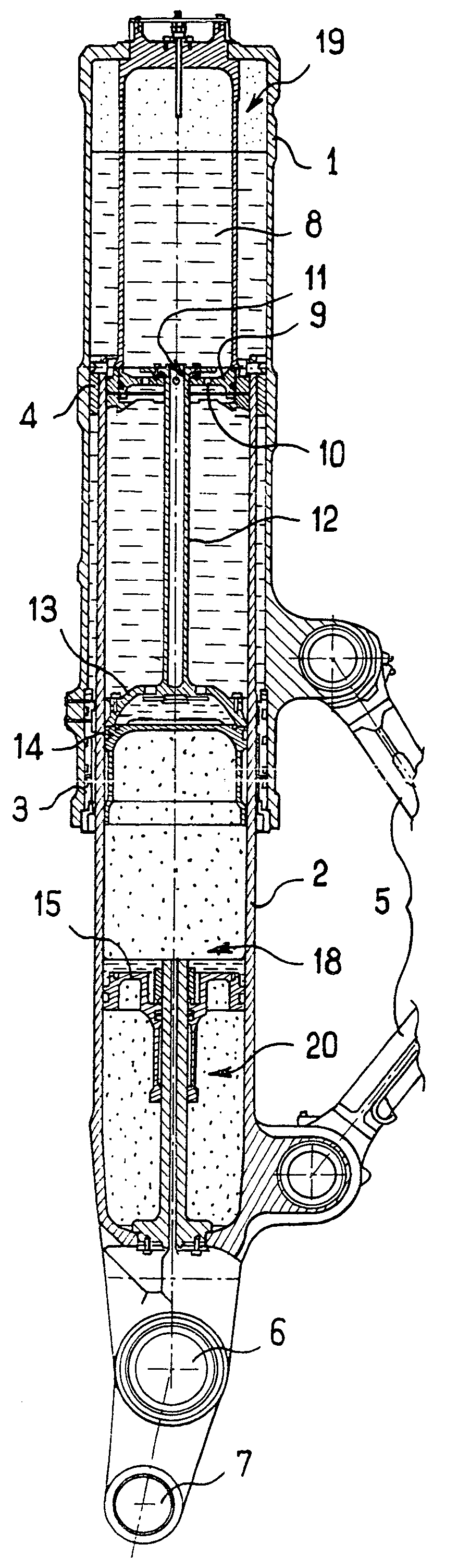
[0017] The invention is applied herein to a direct type undercarriage with an integrated shock absorber mounted under the fuselage of an airplane. Clearly the invention is not limited to undercarriages of this type, and is also applicable to undercarriages having an external shock absorber, and not necessarily mounted under the fuselage.

[0018] With reference to FIG. 1, and in conventional manner, the undercarriage comprises a main strut 1 connected to the airplane and having a rod 2 mounted to slide in leaktight manner therein. For this purpose, the strut carries a bottom bearing 3 in its lower portion with an inside surface in contact with the rod 2, and the rod 2 carries at its top portion a top bearing 4 with an outside surface in contact with the strut 1.

[0019] A scissors linkage 5 (of which only the ends of its two branches are visible) is mounted between the strut 1 and the rod 2 to prevent the rod 2 turning about its axis relative to the strut 1.

[0020] At its bottom end, t...


PUM


Abstract

The invention relates to landing gear including a shock absorber having fist and second elements slidable relative to each other, the slidable elements defining an inside volume which is filled in part with hydraulic fluid so as to leave a first chamber filled with gas under pressure and located at the end of one of the slidable elements. According to the invention, a vessel filled with gas under pressure is housed in the end and is provided with a shutter member that is initially in a closed state and that is suitable for taking up a stable open state when the pressure in the first chamber exceeds the pressure in the vessel by a predetermined threshold amount.

Description

BACKGROUND OF THE INVENTION [0001] Undercarriages are known that include a shock absorber having first and second elements that are slidable relative to each other, said slidable elements defining an internal volume that is partially filled with hydraulic fluid so as to leave respective first and second chambers in the ends of the slidable elements, which chambers are filled with gas under pressure. [0002] In general, the shock absorber includes a diaphragm secured to one of the elements and presenting throttling orifices through which the hydraulic fluid is forced in the event of a shock driving the elements towards each other. Such throttling dissipates a fraction of the kinetic energy of the airplane that has led to the shock absorber being compressed. [0003] Another fraction of the kinetic energy is absorbed by compressing the gas contained in the chambers, given that said chambers decrease in volume during a shock. [0004] For undercarriages situated beneath the fuselage of an a...

Claims


Application Information

Patent Timeline
Patent Type & Authority Applications(United States)
IPC IPC(8): B64C25/60F16F9/06
CPCF16F9/064B64C25/60
Inventor MARTINEZ, LAURENTGILLET, MARCGAUTRAIN, SEBASTIENCOURTOIS, MAUD
Owner MESSIER DOWTY
Why Eureka
Try Eureka