
Electrical connector including a bayonet locking device

a technology of electrical connectors and locking devices, applied in the direction of coupling device connections, instruments, optical elements, etc., can solve the problems of affecting the installation of battery packs on the helmet, affecting the installation of battery packs, and affecting the use of helmets

Active Publication Date: 2010-06-22
ELBIT SYSTEMS OF AMERICA LLC
View PDF33 Cites 71 Cited by
  • Summary
  • Abstract
  • Description
  • Claims
  • Application Information

AI Technical Summary

Problems solved by technology

The foregoing steps for mounting the battery pack onto the helmet may be perceived as difficult and inconvenient for some users, especially for those with limited dexterity.
More particularly, manipulating the hot shoe connector is sometimes made difficult by the possibility that the user is blindly reaching to the side or rear of his or her head and manipulating the battery pack and / or the helmet until the proper orientation is achieved.
These factors hinder the installation of battery packs onto the helmet, which can be problematic in a battle scenario.

Method used


Image

  • Electrical connector including a bayonet locking device
  • Electrical connector including a bayonet locking device
  • Electrical connector including a bayonet locking device

Examples


Embodiment Construction

[0030]This invention will now be described with reference to several embodiments selected for illustration in the drawings. It will be appreciated that the scope and spirit of the invention are not limited to the illustrated embodiments.

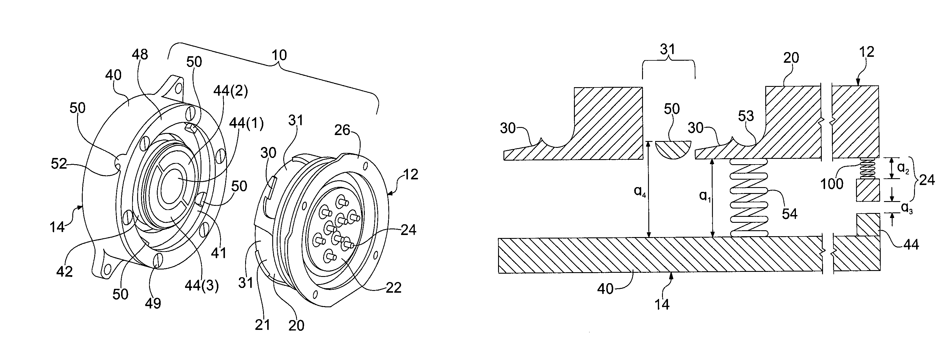
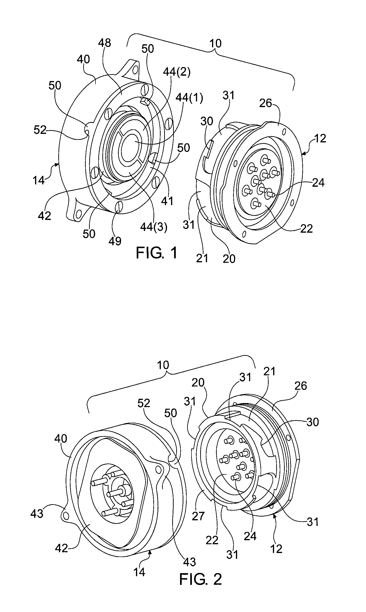
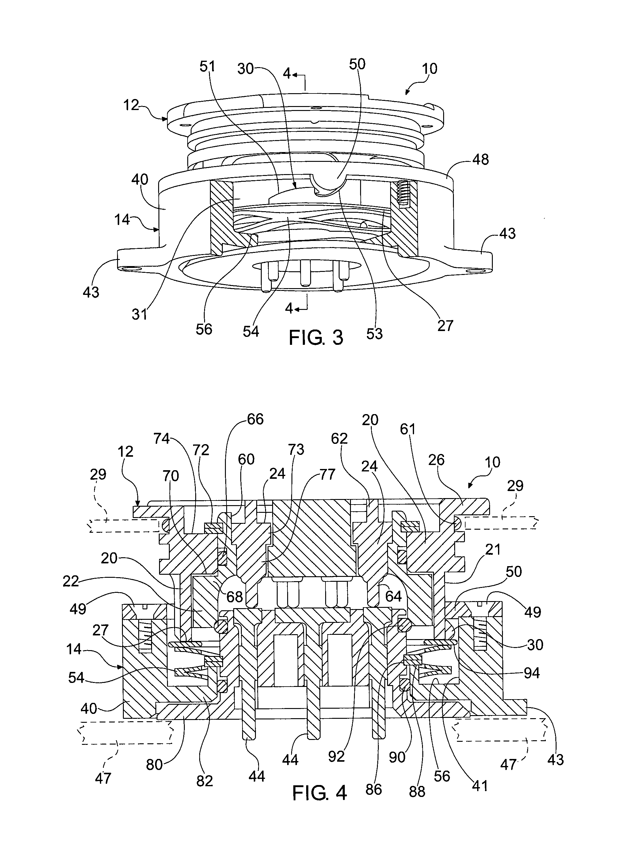
[0031]As used herein, the term ‘connector’ refers to a device that provides an electrical connection between two elements, a mechanical connection between two elements, or both. The term ‘connector’ may also refer to a single component, such as a plug or a receptacle, for example, that is employed to mate with another component to establish a connection therebetween.

[0032]FIGS. 1 and 2 depict perspective views of a connector 10, according to one exemplary embodiment of the invention. The connector 10 may be referred to herein as a rotary hot shoe connector or a roto-shoe connector. The connector 10 generally includes a plug assembly 12 and a receptacle assembly 14. The plug assembly 12 is shown separated from the receptacle assembly 14 in FIGS. 1 and...


PUM


Abstract

An electrical connector for a helmet-mounted night vision system, or other electronic device, is provided. The electrical connector includes a plug assembly and a receptacle assembly each including a body having a revolved surface and an electrical contact. A protrusion extends from the revolved surface of either the plug assembly or the receptacle assembly and a cam surface is defined along the revolved surface of the other of the plug assembly and the receptacle assembly. Upon engagement between the assemblies, the revolved surfaces of the assemblies are positioned to face each other and upon rotation of the assemblies with respect to one another the protrusion is positioned to move along the cam surface causing the electrical contact of the plug assembly to bear against the electrical contact of the receptacle assembly thereby establishing a connection between the plug assembly and the receptacle assembly.

Description

TECHNICAL FIELD[0001]This invention generally relates to a connector for electronic devices. More particularly, it relates to a connector that is suitable for night vision systems.BACKGROUND OF THE INVENTION[0002]Hot-shoe connectors are commonly used to provide a mechanical means of attachment as well as an electrical connection between two devices. By way of example, many conventional cameras incorporate hot shoe connectors for mounting flash units thereto. A hot-shoe receptacle is located on the top side of a camera, and a hot-shoe plug is disposed on the bottom end of the flash unit for attaching the flash unit to the hot-shoe receptacle of the camera. In assembly, the hot-shoe plug on the flash unit is slidably inserted into the hot-shoe receptacle on the camera. The plug and receptacle may be secured together by a clamping screw that is provided on the flash, or other means. In the center of the hot-shoe receptacle on the camera is a metallic contact that interfaces with a meta...

Claims


Application Information

Patent Timeline
Patent Type & Authority Patents(United States)
IPC IPC(8): H01R13/625
CPCH01R13/625F41H1/04G02B23/12
Inventor WILLEY, CHARLES D.BANDY, GREGORY S.DAMIANO, KYLE
Owner ELBIT SYSTEMS OF AMERICA LLC
Learn More