
Lithium polymer battery powered intravenous fluid warmer

a lithium polymer battery and fluid warmer technology, applied in the direction of heater elements, electric devices, safety/protection circuits, etc., can solve the problems of limiting the portability of the battery-powered fluid warmer, unable to be fast charged, and long charge time of about 12 hours, so as to avoid overcharging and overcharging conditions

Inactive Publication Date: 2010-06-22
VITAL SIGNS INC
View PDF29 Cites 26 Cited by
  • Summary
  • Abstract
  • Description
  • Claims
  • Application Information

AI Technical Summary

Problems solved by technology

Battery powered IV fluid warmers have heretofore had poor performance because of the battery sources which have been available.
Thermal Angel uses a 12 volt lead acid battery which is heavy, weighing about 7 pounds, limiting its portability.
It has a long charge time of about 12 hours and cannot be fast charged.
In addition, the device has only a minimal gas gauge which is only accurate when the battery is not in use.
However, such batteries can be dangerous if overcharged or overdischarged and in such circumstances the batteries can explode or catch fire.

Method used


Image

  • Lithium polymer battery powered intravenous fluid warmer
  • Lithium polymer battery powered intravenous fluid warmer
  • Lithium polymer battery powered intravenous fluid warmer

Examples


first embodiment

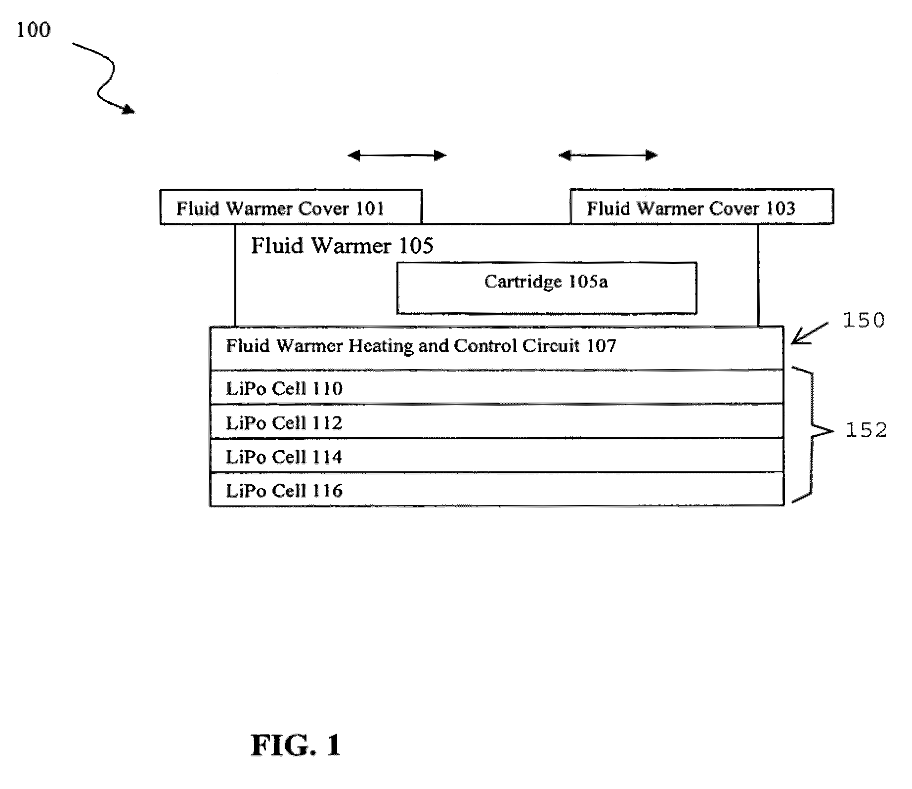
[0030]FIG. 1 illustrates a fluid warmer assembly 100 according to the present invention. A fluid warmer 105 has a fluid warmer cover 101 and a fluid warmer cover 103. The arrows above the fluid warmer cover 101 and the fluid warmer cover 103 show the respective bidirectional capability of movement. The fluid warmer cover 101 and the fluid warmer cover 103 include a switch (not shown) that generates a fluid warmer cover closure signal 244, described below, indicating whether the fluid warmer covers 101, 103 are open or closed.

[0031]A unitary housing includes the fluid warmer 105, monitoring and control electronics, and the rechargeable cells. Specifically, the fluid warmer 105 is disposed on a fluid warmer heating and control circuit 107, which includes a group of rechargeable Lithium Polymer cells, namely, LiPo cells 110, 112, 114, and 116. In a preferred embodiment, the fluid warmer assembly 100 has a removable cartridge 105a to which a fluid line is attached and through which flui...

second embodiment

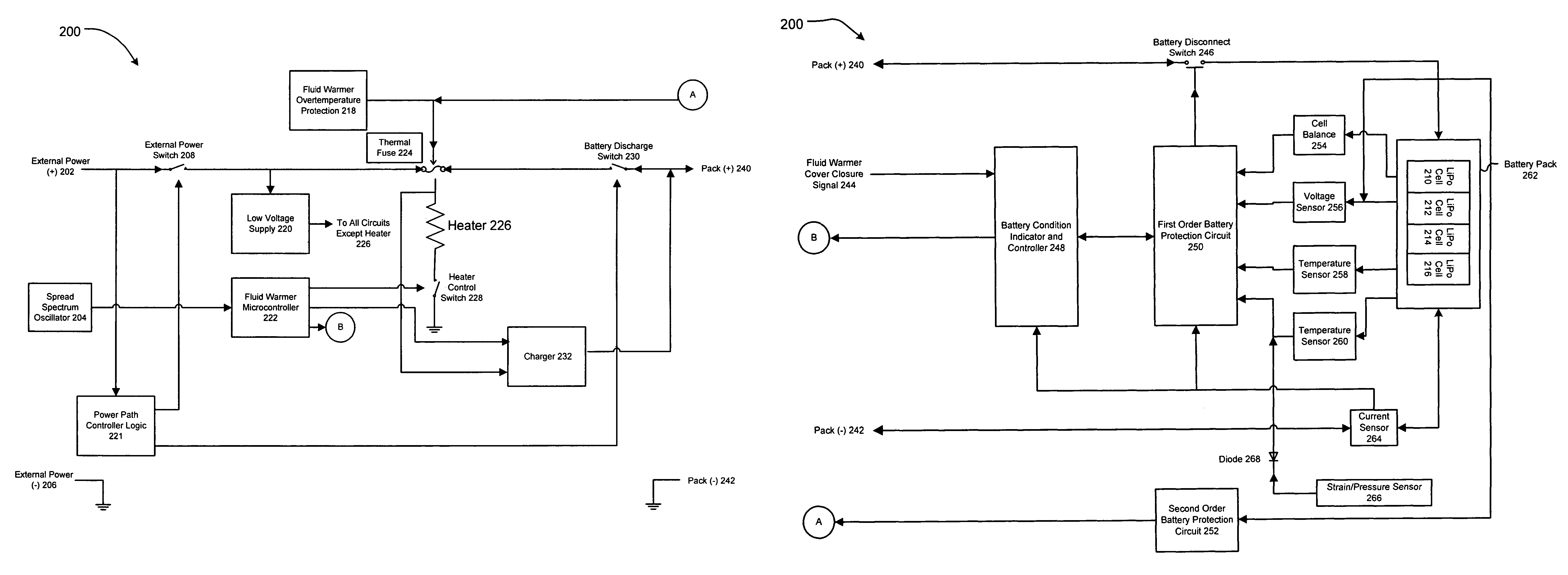
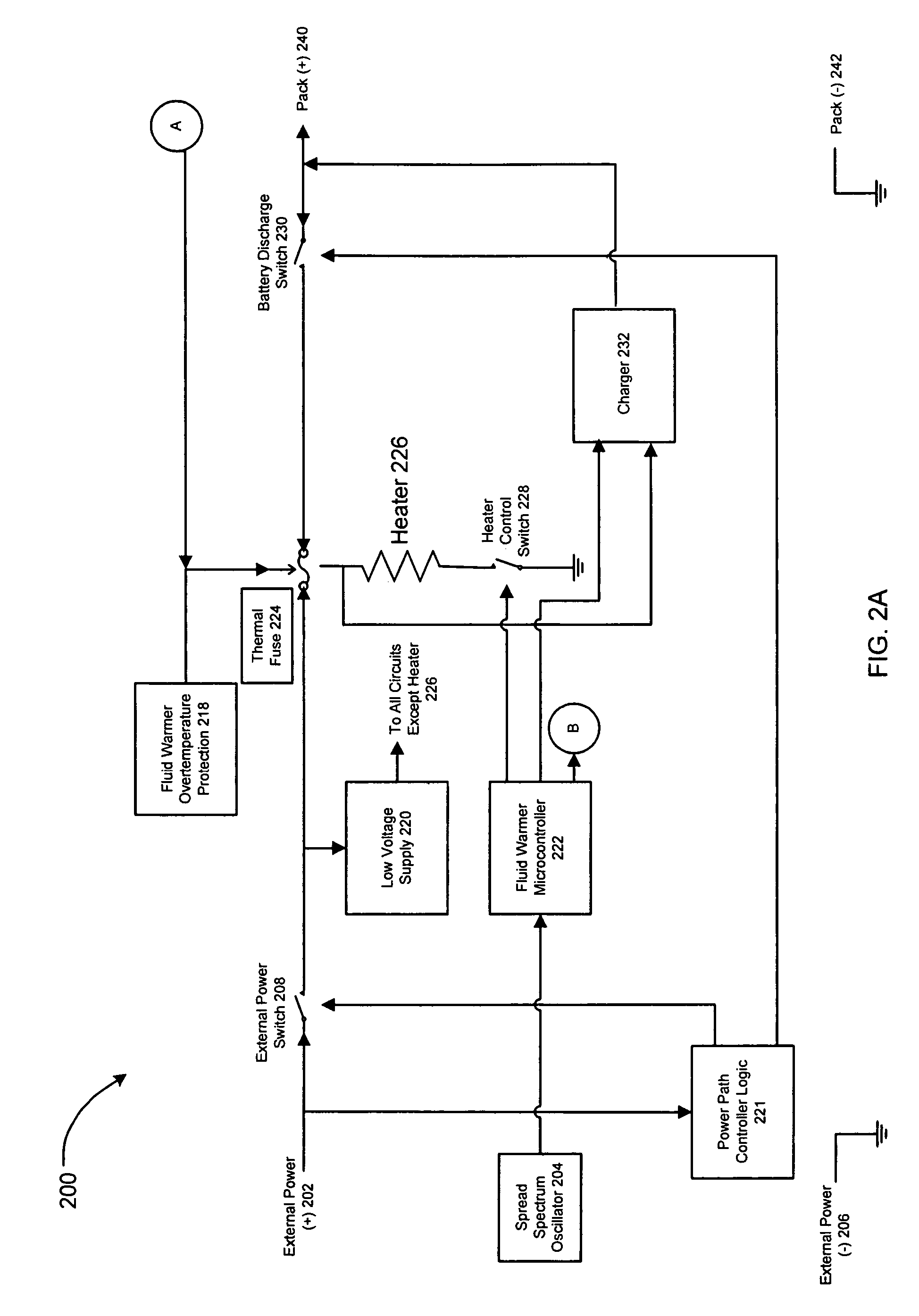
[0046]FIG. 3 illustrates a fluid warmer heating and control circuit 300 according to the present invention. As an illustration, eight LiPo cells, namely, 310, 312, 314, 316, 310A, 312A, 314A, and 316A, are connected in series and included in a battery pack 362. Each of the LiPo cells is connected to a first order battery protection circuit 350, a second order battery protection circuit 352 and a cell balance circuit 354. The first order battery protection circuit 350 and the cell balance circuit 354 are connected to a fluid warmer controller 322 which also receives temperature information from a temperature sensor 358 and from an ambient temperature sensor 372. The fluid warmer controller 322 is in communication with a charger 332. The fluid warmer controller 322 communicates with a controller of an IV fluid warmer system (not shown) via a data input / output 341. A UART included in the fluid warmer controller 322 can be used for data transfer. The fluid warmer controller 322 is also ...


PUM


Abstract

A lithium polymer (LiPo) battery pack having LiPo battery cells is provided which includes battery protection circuitry, charging circuitry, cell balancing circuitry, and control and communication circuitry. The batteries can be charged while in use by an internal charger. Battery charging and discharging are accomplished in a controlled and protected manner to avoid overcharging and overdischarging conditions. The novel battery pack has built-in safeguards against dangerous LiPo battery conditions and is implemented in a small, portable unit which contains the battery cells, control and protection circuitry, internal charger and display gauge. The battery pack is useful for powering an intravenous fluid warmer or other medical or electrical devices and equipment.

Description

CROSS REFERENCE TO RELATED APPLICATIONS[0001]The present application claims priority under 35 U.S.C. 119(e) of U.S. Provisional Patent Application titled LITHIUM POLYMER BATTERY PACK, Application No. 60 / 734,108 filed on Nov. 7, 2005.TECHNICAL FIELD OF THE INVENTION[0002]This invention is generally related to battery-operated fluid warmers and, in particular, to fluid warmers running on batteries including lithium polymer rechargeable cells.STATEMENT REGARDING FEDERALLY SPONSORED RESEARCH OR DEVELOPMENT[0003]Not applicableBACKGROUND OF THE INVENTION[0004]Intravenous (IV) fluid warmers have traditionally been powered by an AC power source because of the high power required to heat IV fluids. Battery powered IV fluid warmers have heretofore had poor performance because of the battery sources which have been available.[0005]The battery requirements for IV fluid warmers include the following:[0006]1. Small size and weight for easy portability,[0007]2. Extremely high discharge rates (very...

Claims


Application Information

Patent Timeline
Patent Type & Authority Patents(United States)
IPC IPC(8): H02J7/04
CPCA61M5/44H01M10/052H01M10/0565H01M10/425H01M10/46H01M10/482H01M10/486H02J7/0031B60L3/0046B60L11/1859B60L11/1872B60L11/1875Y02T10/7005H01M10/488H01M2010/4271H01M2010/4278H01M2220/30H02J7/0026B60L2240/545B60L2250/16Y02E60/122Y02T10/705Y02T90/16Y02T10/7011A61M2205/8206H01M2200/103B60L58/14B60L58/25B60L58/27B60L58/15H02J7/00309B60L58/24B60L58/22H02J7/0013Y02E60/10Y02T10/70H02J2310/23
Inventor CASSIDY, DAVID
Owner VITAL SIGNS INC
Learn More