
Selectable one-way rocker clutch

a one-way, rocker clutch technology, applied in the direction of mechanical actuated clutches, interengaging clutches, gearing, etc., can solve the problems of engine operating at a specific fuel consumption level and limited overall speed range of the vehicl

Inactive Publication Date: 2010-06-29
GM GLOBAL TECH OPERATIONS LLC
View PDF20 Cites 75 Cited by
  • Summary
  • Abstract
  • Description
  • Claims
  • Application Information

AI Technical Summary

Benefits of technology

[0007]A selectable one-way rocker clutch assembly is provided having a first race radially disposed with respect to a second race. The first race defines a plurality of pockets, whereas the second race defines a plurality of teeth. A plurality of rockers is at least partially positioned within respective ones of the plurality of pockets and is configured to engage with the teeth of the second race to thereby resist or prevent rotation of the first race relative to the second race. The selectable one-way rocker clutch assembly also includes a selector member radially disposed with respect to the first and second races. The selector member is selectively rotatable between at least a first and a second position, and configured to prevent engagement of at least one of the plurality of rockers with the teeth of the second race when the selector is in the second position.

Problems solved by technology

This severely limited the overall speed range of the vehicle and therefore required a relatively large engine that could produce a wide speed and torque range.
This resulted in the engine operating at a specific fuel consumption level during cruising, other than the most efficient level.

Method used


Image

  • Selectable one-way rocker clutch
  • Selectable one-way rocker clutch
  • Selectable one-way rocker clutch

Examples


Embodiment Construction

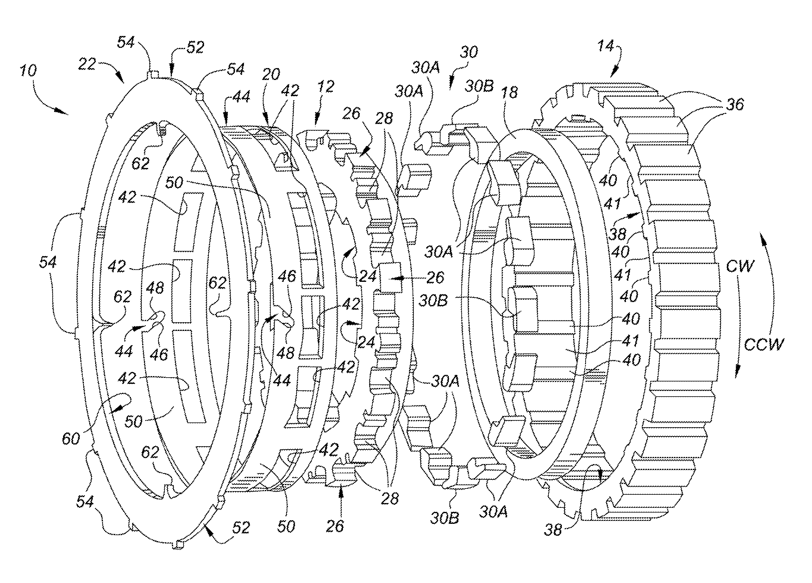
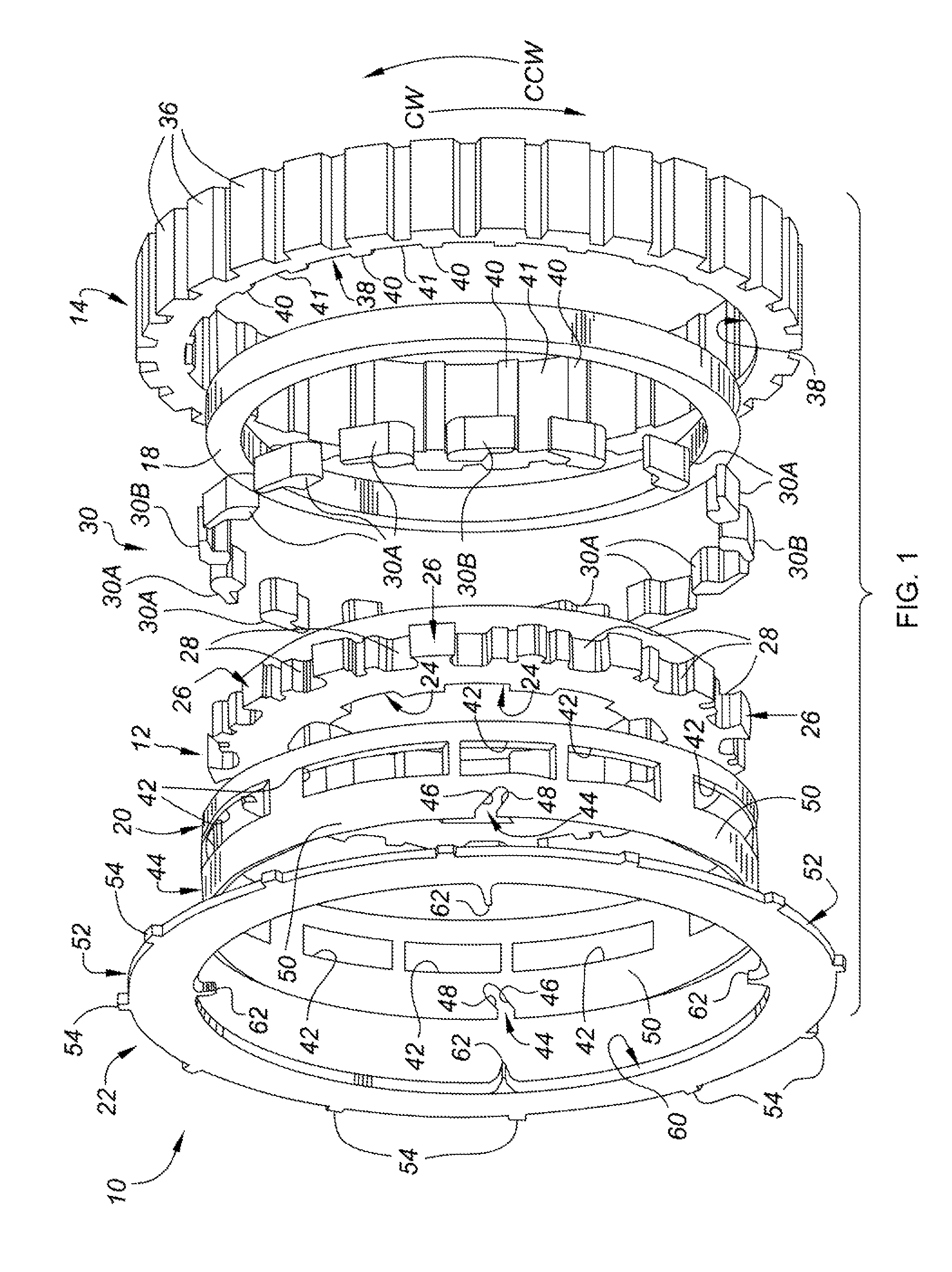
[0027]Referring to the drawings wherein like reference numbers refer to like components, FIG. 1 shows an exploded view of a selectable one-way rocker clutch assembly 10. The rocker clutch assembly 10 is controllable to transmit torque in two rotational directions (i.e., clockwise and counter clockwise), or to transmit torque in one direction and overrun (i.e., freewheel in a disengaged state) in the opposite direction. The rocker clutch assembly 10 may be used, for example, to control the torque transfer in an automatic transmission, a manual transmission, a hybrid vehicle transmission, a dual clutch transmission, a transfer case, or an engine accessory drive.

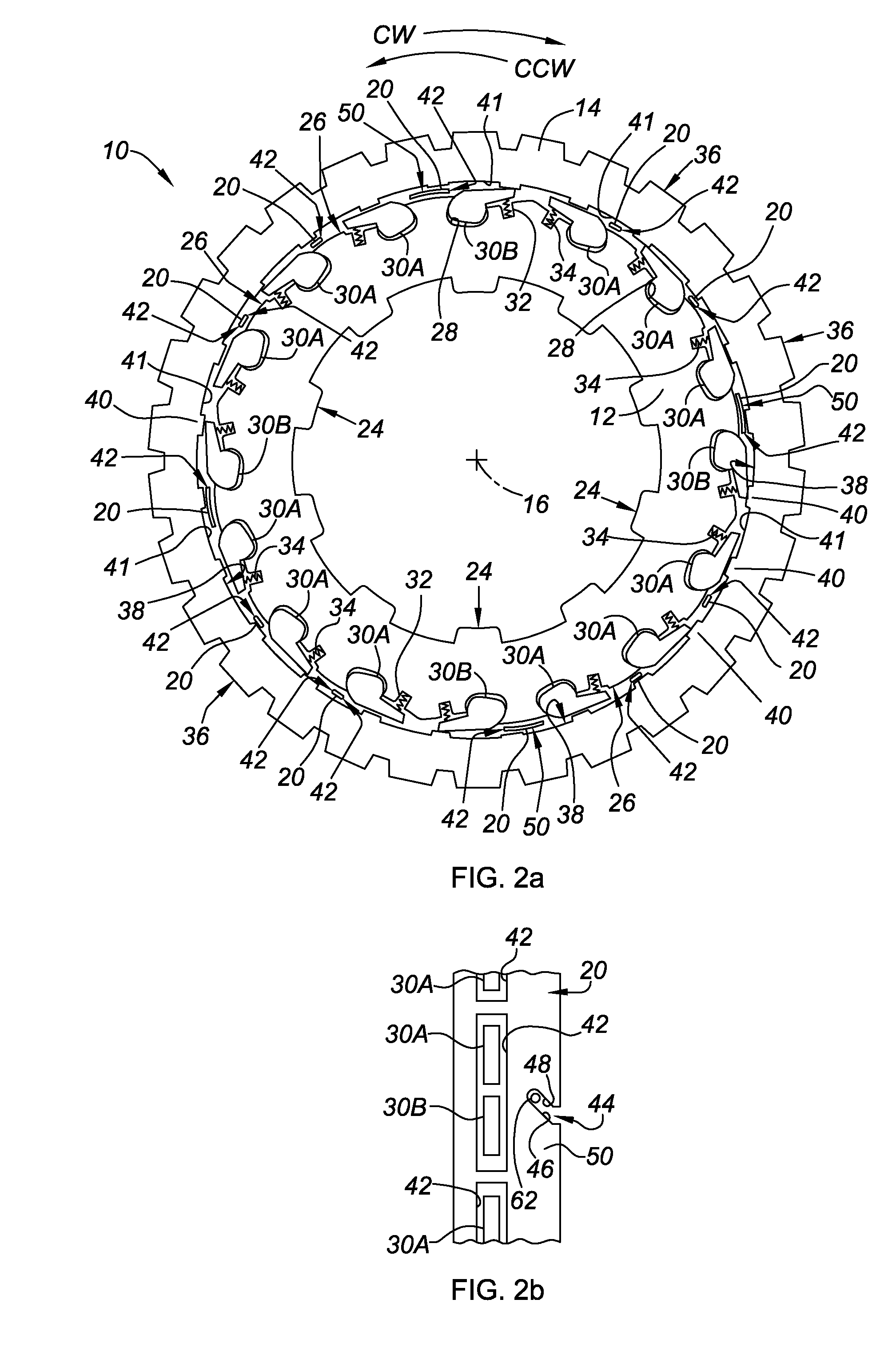
[0028]The rocker clutch assembly 10 includes a generally annular inner race 12 and a generally annular outer race 14, with the inner and outer races 12, 14 positioned coaxially about an axis of rotation 16 (best seen in FIG. 2a). A bushing 18 is preferably provided to pilot or guide the outer race 14 as it rotates relative to t...


PUM


Abstract

A selectable one-way rocker clutch assembly includes an inner race disposed radially within an outer race, first and second plurality of rockers, a selector ring and an apply plate. The inner race defines a plurality of pockets configured to operatively retain the first and second plurality of rockers. The first plurality of rockers is configured to resist rotation of the outer race relative to the inner race in a first direction. The second plurality of rockers is configured to resist rotation of the outer race relative to the inner race in a second direction. The selector ring is disposed radially between the inner race and outer race. The apply plate is configured to engage with the selector ring and, in so doing, rotate the selector ring to thereby selectively retract the first and / or second plurality of rockers and thus control the state of the rocker clutch assembly.

Description

CROSS REFERENCE TO RELATED APPLICATIONS[0001]This application claims priority to U.S. Provisional Patent Application No. 60 / 803,556, filed on May 31, 2006, which is hereby incorporated by reference in its entirety.TECHNICAL FIELD[0002]The present invention pertains generally to rocker clutches having selectively variable modes of operation.BACKGROUND OF THE INVENTION[0003]Traditional automotive vehicles include a powertrain that is comprised of an engine, a multi-speed transmission, and a differential or final drive system. The multi-speed transmission increases the overall operating range of the vehicle by permitting the engine to operate through its torque range a number of times. The number of forward speed ratios that are available in the transmission is indicative of the number of times the engine torque range is repeated.[0004]Automatic transmissions (e.g., planetary gear type) and manual shifting transmissions (e.g., countershaft type) constitute the two main varieties of aut...

Claims


Application Information

Patent Timeline
Patent Type & Authority Patents(United States)
IPC IPC(8): F16H3/08F16H3/38F16D11/06F16D13/04
CPCF16D41/16F16H3/10Y10T74/19228Y10T74/19284F16H57/08F16D41/14
Inventor WITTKOPP, SCOTT H.HART, JAMES M.CAREY, CLINTON E.
Owner GM GLOBAL TECH OPERATIONS LLC
Learn More