Folded horn enclosure with unitary pathway

a horn enclosure and unitary pathway technology, applied in the direction of transducer diaphragms, electrical apparatus casings/cabinets/drawers, instruments, etc., can solve the problems of reducing or preventing the deleterious effects, particularly providing efficient use, and limiting the use of front-loaded corner horn enclosures in the prior art, so as to optimize the low frequency response and reduce the footprint. , the effect of high efficiency

Inactive Publication Date: 2010-06-29
MOORE DANA A
View PDF16 Cites 14 Cited by
  • Summary
  • Abstract
  • Description
  • Claims
  • Application Information

AI Technical Summary

Benefits of technology

[0007]It is an additional object of the current invention to provide the ability to operate the current invention in a horizontal or vertical placement.
[0008]It is a further object of the current invention to provide, in one embodiment, efficient corner placement and operation for optimized low frequency response and high efficiency by the invention's outward shape.
[0009]It is still another object of the current invention to provide for the easy scaling to use an 18-inch or larger diameter driver by altering a single dimension of the invention only.

Problems solved by technology

Front-loaded corner horn enclosures of the prior art have typically not been designed with the idea of effectively operating either vertically or horizontally in other radiating angles in addition to placement in a corner.
Although rectangular-shaped horn enclosures might find themselves occasionally placed in a corner for enhanced low frequency response, such enclosures are not particularly optimized for corner operation, and while gaining a low frequency acoustic advantage of some degree from the proximate corner wall / floor boundaries, the rectangular outward shape of such an enclosure does not particularly provide an efficient use of the corner space; nor does it maximize the potential acoustic benefits of such a placement; and further, it does not lessen or prevent the deleterious effects of cabinet and / or horn mouth diffraction; the effects of which may be compounded by the common inability of a rectangular parallelepiped form with a rectangular footprint to effectively and efficiently couple acoustically with the reflective surfaces provided by a corner.

Method used


Image

  • Folded horn enclosure with unitary pathway
  • Folded horn enclosure with unitary pathway
  • Folded horn enclosure with unitary pathway

Examples


Embodiment Construction

[0018]The current invention features at least 2 different flare rates, with the overall low frequency cutoff (Fc) being mostly determined by the terminal flare rate of 38 Hz.

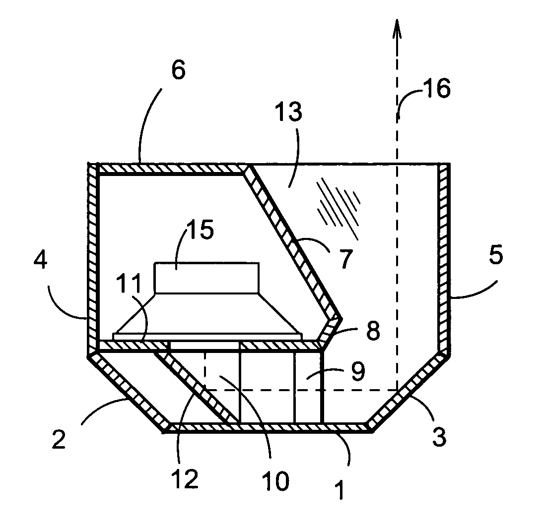
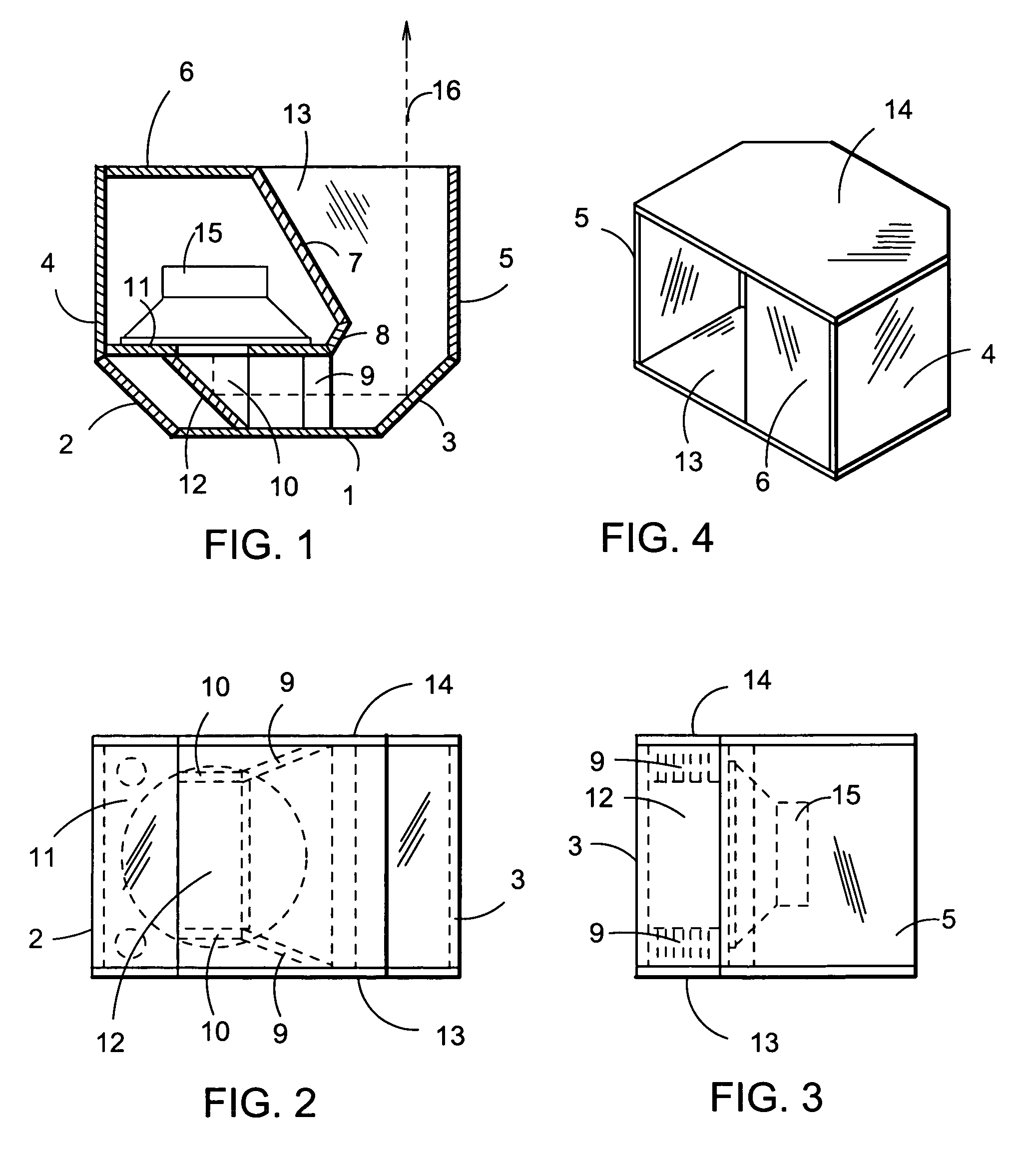
[0019]In the present disclosure, a 15-inch driver 15 is shown. The current invention provides for the use of an 18-inch driver by increasing the vertical height of the enclosure as shown in FIG. 2, without modification to any other dimensions other than suitably increasing the throat opening area also. Additional back chamber volume (Vb) can be achieved by increasing the overall depth of the invention. The Vb shown is approximately 5300 cubic inches.

[0020]Referring to FIG. 1, the horn sound path is shown by dotted line 16. The pathway contains two 90-degree folds or turns. Waveform “phase” is reversed across the horn channel (as with a mirrored reflection) twice by the full channel reflectors and emerges at the mouth “in phase” with the original waveform, allowing the higher frequencies to transit the folds with...


PUM


Abstract

A folded horn enclosure including a unitary throat and horn pathway which is optimized for ⅛th space placement when operated as a stacked pair. The enclosure uses at least 2 different flare rates and is suitable for standing vertically and horizontally, and further allowing stacking of 2 enclosures to form a full-sized corner horn.

Description

BACKGROUND OF THE INVENTION[0001]The present invention relates to folded horn loudspeaker enclosures. Specifically, it relates to front-loaded low frequency horn enclosures that may be used in various radiating angles comprised of at least one or more acoustically reflective surface. The present invention is relatively equally efficient standing vertically or horizontally regardless of the acoustic load present.[0002]The current invention relates directly to my previous U.S. patent application Ser. No. 11 / 900,534 titled “Convertible Folded Horn with Improved Compactness” and can be considered a contribution over my previous invention in that it provides essentially the same level of performance and efficiency, is easy to construct, and provides the increase utility of being able to operate effectively whether placed horizontally or vertically which provides the ability to better operate as a single-driver unit with a smaller footprint depending on the placement, along with an option...

Claims


Application Information

Patent Timeline
Patent Type & Authority Patents(United States)
IPC IPC(8): H05K5/00G10K11/00G10K13/00H04R1/20H04R7/00
CPCH04R1/2865G10K11/025
Inventor MOORE, DANA A.
Owner MOORE DANA A
Why Eureka
Try Eureka