Apparatus for lifting building foundations

a technology for building foundations and apparatuses, applied in the field of systems for lifting and/or stabilizing foundations, can solve problems such as system drawbacks

Active Publication Date: 2010-06-29
PIERTECH
View PDF25 Cites 42 Cited by
  • Summary
  • Abstract
  • Description
  • Claims
  • Application Information

AI Technical Summary

Problems solved by technology

Despite the variety of lifting systems currently available, these systems suffer from several drawbacks.

Method used


Image

  • Apparatus for lifting building foundations
  • Apparatus for lifting building foundations
  • Apparatus for lifting building foundations

Examples


Embodiment Construction

[0037]The following description of the preferred embodiment(s) is merely exemplary in nature and is in no way intended to limit the invention, its application, or uses.

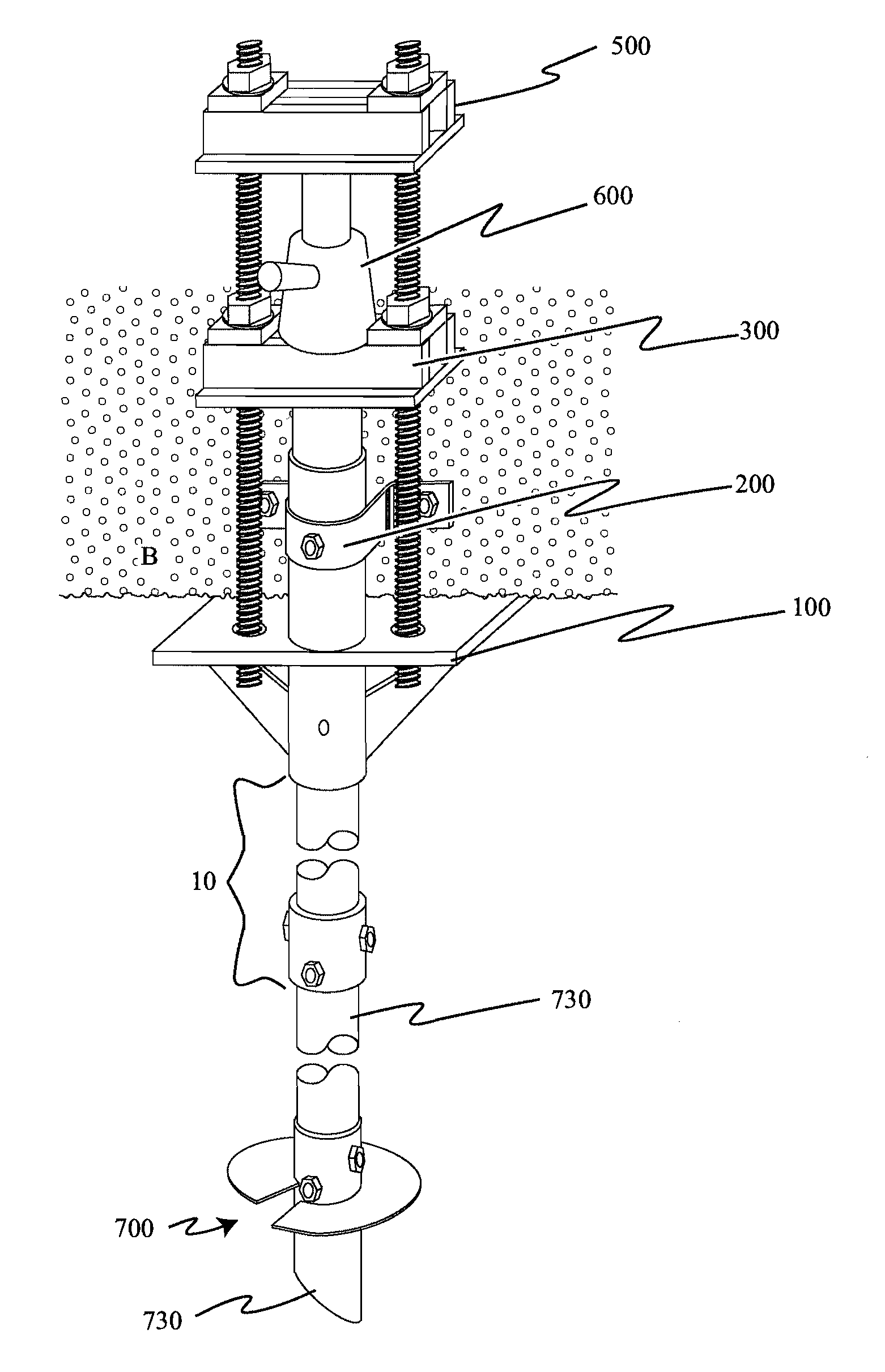
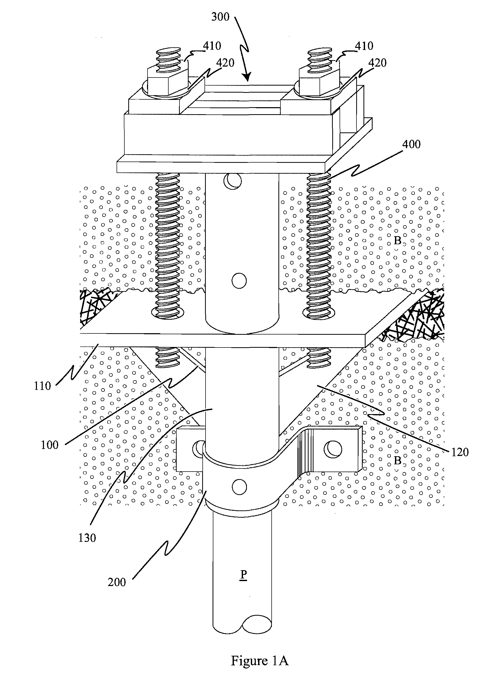
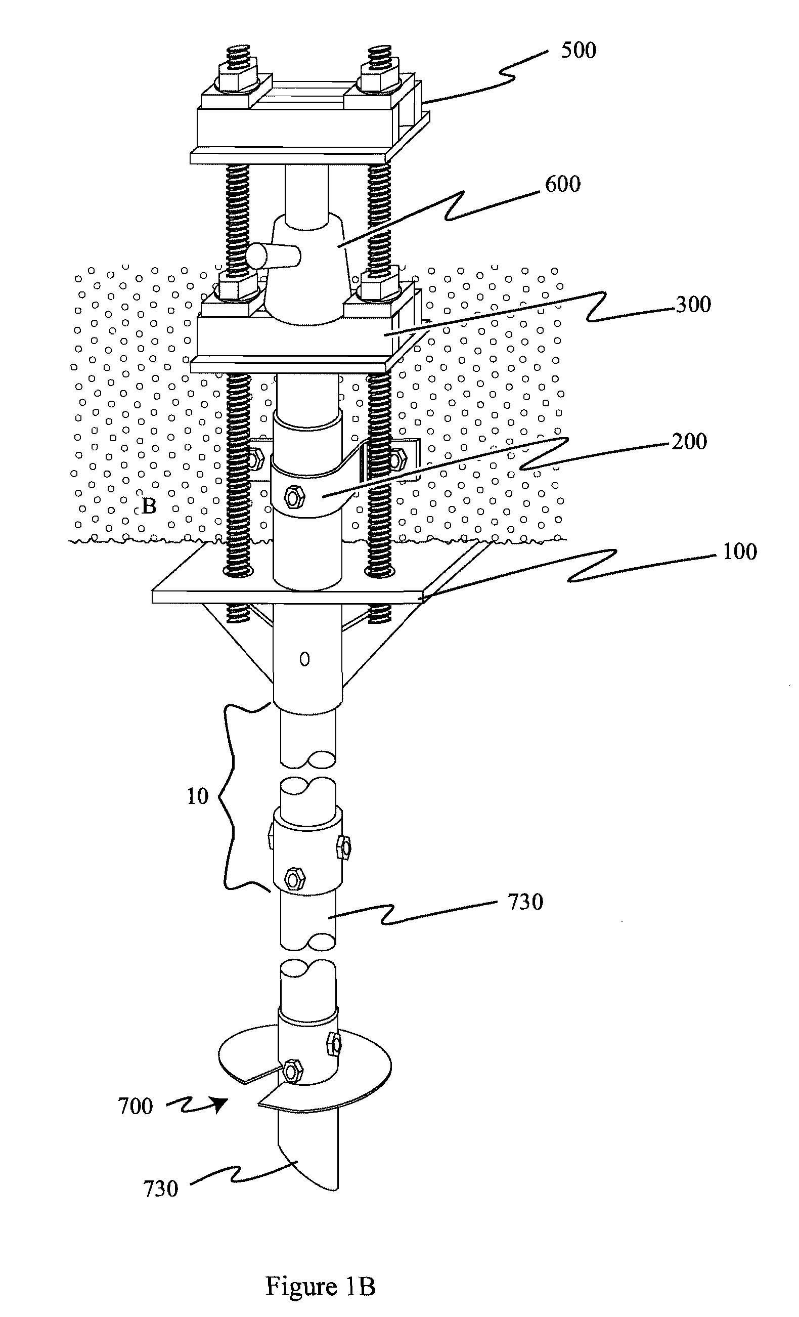
[0038]After determining how the building or other structure needs to be lifted or supported, piles or pipes (hereinafter collectively referred to as a “pile” or “piles”) P attached to foundation piers or the like are set into the ground near the structure using known methods. The piers typically consist of a long shaft driven into the ground, upon which a lifting assembly is assembled. The shaft of the pier may include one or more lateral projections such as a helical auger to provide further support for the pier by providing a larger surface area. In some cases one or more extension pieces may be attached to the pier to extend it to the height of the building or to adapt a pile with a non-circular cross-section to a circular cross-section, as discussed below. The lifting assembly (FIGS. 1A, 1B) is then attached to th...


PUM


Abstract

A lift bracket system for lifting a building structure such as a foundation and the like comprising a lift plate having a top surface and a bottom surface, the top surface for insertion under the building structure; a generally cylindrical housing affixed to the lift plate and extending perpendicularly from the top surface and the bottom surface of the lift plate, the housing defining a generally circular opening through the lift plate, the opening being disposed away from the center of the lift plate; and at least one gusset for supporting the lift plate, the gusset having a first end and a second end, the gusset disposed beneath the lift plate, wherein the first end of the gusset is attached to the bottom surface of the lift plate and the second end of the gusset is attached to the housing.

Description

CROSS-REFERENCE TO RELATED APPLICATIONS[0001]None.BACKGROUND OF THE INVENTION[0002]1. Field of the Invention[0003]The present invention relates generally to tools, equipment, and fixtures used in the building and construction trades, and more specifically to a system for lifting and / or stabilizing foundations and the like.[0004]2. Related Art[0005]As buildings age and settle there is sometimes a need for lifting or jacking the building foundation to make all parts of the building approximately level, which in turn repairs and prevents further damage to the building structure. There are numerous designs known in the art for systems for stabilizing and lifting building structures. These typically begin with a pier or piling driven or screwed into the ground beneath the building foundation, leaving a piling projecting upwards on which a lifting structure is attached. The lifting structure attaches to the piling and also to the building, with the lifting structure pushing against the pi...

Claims


Application Information

Patent Timeline
Patent Type & Authority Patents(United States)
IPC IPC(8): E02D5/00
CPCE02D35/00E02D35/005
Inventor KAUFMAN, KEVIN
Owner PIERTECH
Why Eureka
Try Eureka