Antenna mounting assembly

a technology for mounting assemblies and antennas, applied in the direction of antennas, antenna details, antenna adaptation in movable bodies, etc., can solve the problems of increased parts, limited working space, and increased parts, and achieve the effect of increasing the number of parts

Inactive Publication Date: 2010-06-29
DENSO CORP
View PDF9 Cites 1 Cited by
  • Summary
  • Abstract
  • Description
  • Claims
  • Application Information

AI Technical Summary

Benefits of technology

[0011]In view of the above and other problems, the present disclosure provides an antenna mounting assembly that allows easy mounting and dismounting of an antenna body without an increase of the number of assembly parts.
[0013]According to this configuration, such first bracket and screws for mounting the antenna assembly to the instrument panel as in the foregoing prior art are no longer needed, and the antenna assembly (here a combined assembly of both the antenna body and bracket) can be mounted on the instrument panel easily without an increase in the number of parts.

Problems solved by technology

Thus, there is a problem of an increase in the number of parts.
Also in this point the problem of an increase in the number of parts is encountered.
However, the working space is limited because many other parts and parts assemblies are installed in the interior of the instrument panel 10.
Thus, the screwing work is not easy.
If the worker should drop any of the screws 14 to the interior of the instrument panel 10 by mistake during the work, it is difficult to recover the dropped screw.

Method used


Image

  • Antenna mounting assembly
  • Antenna mounting assembly
  • Antenna mounting assembly

Examples


Embodiment Construction

[0028]An embodiment of the present invention will be described in the following with reference to the accompanying drawings.

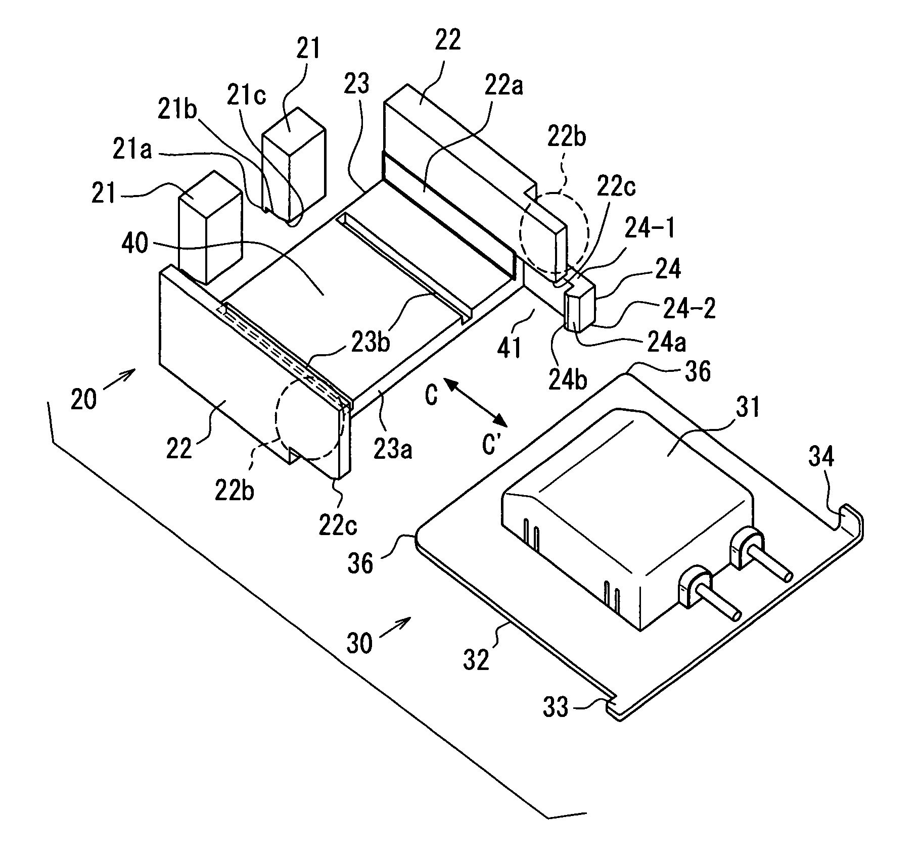
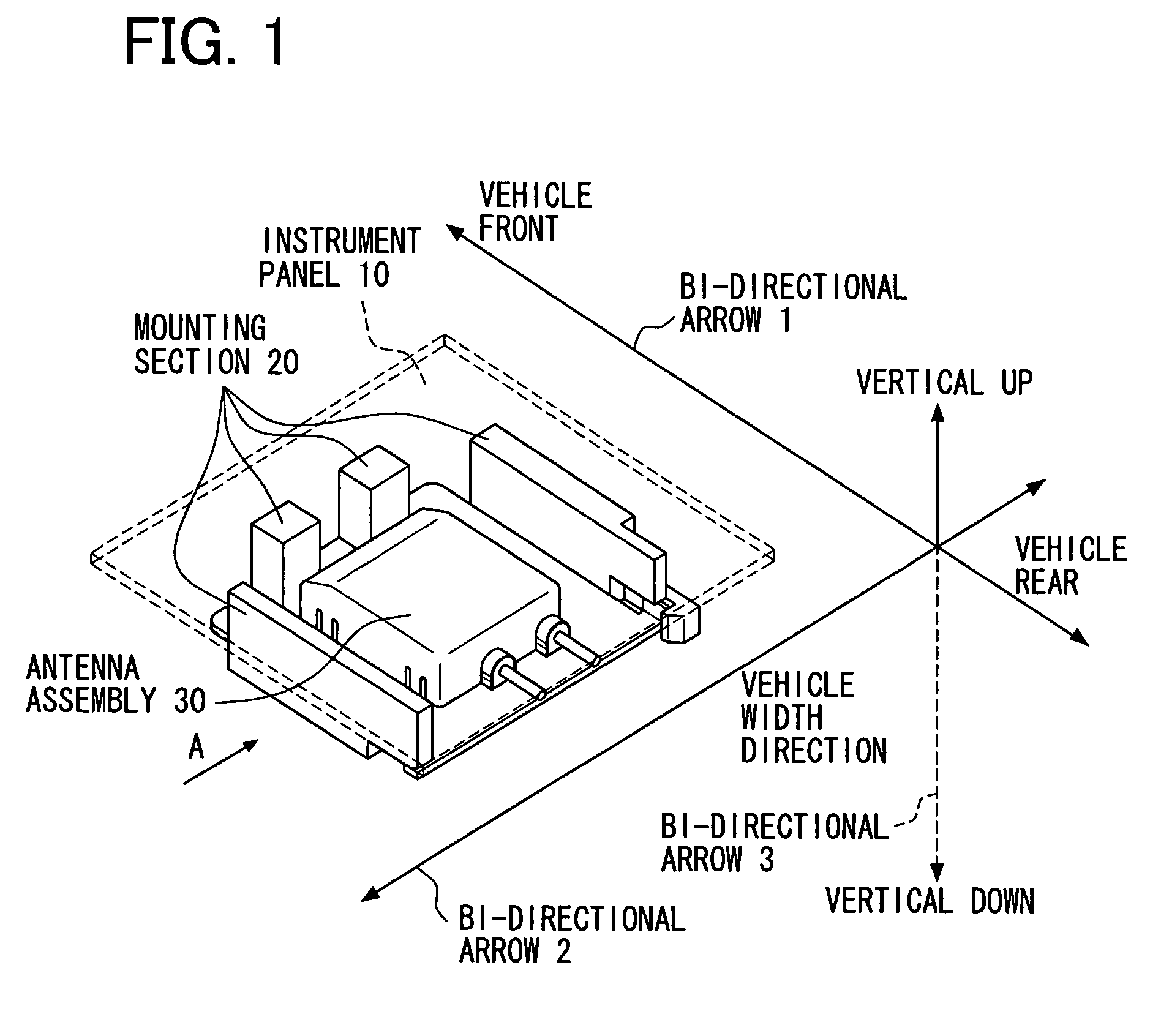
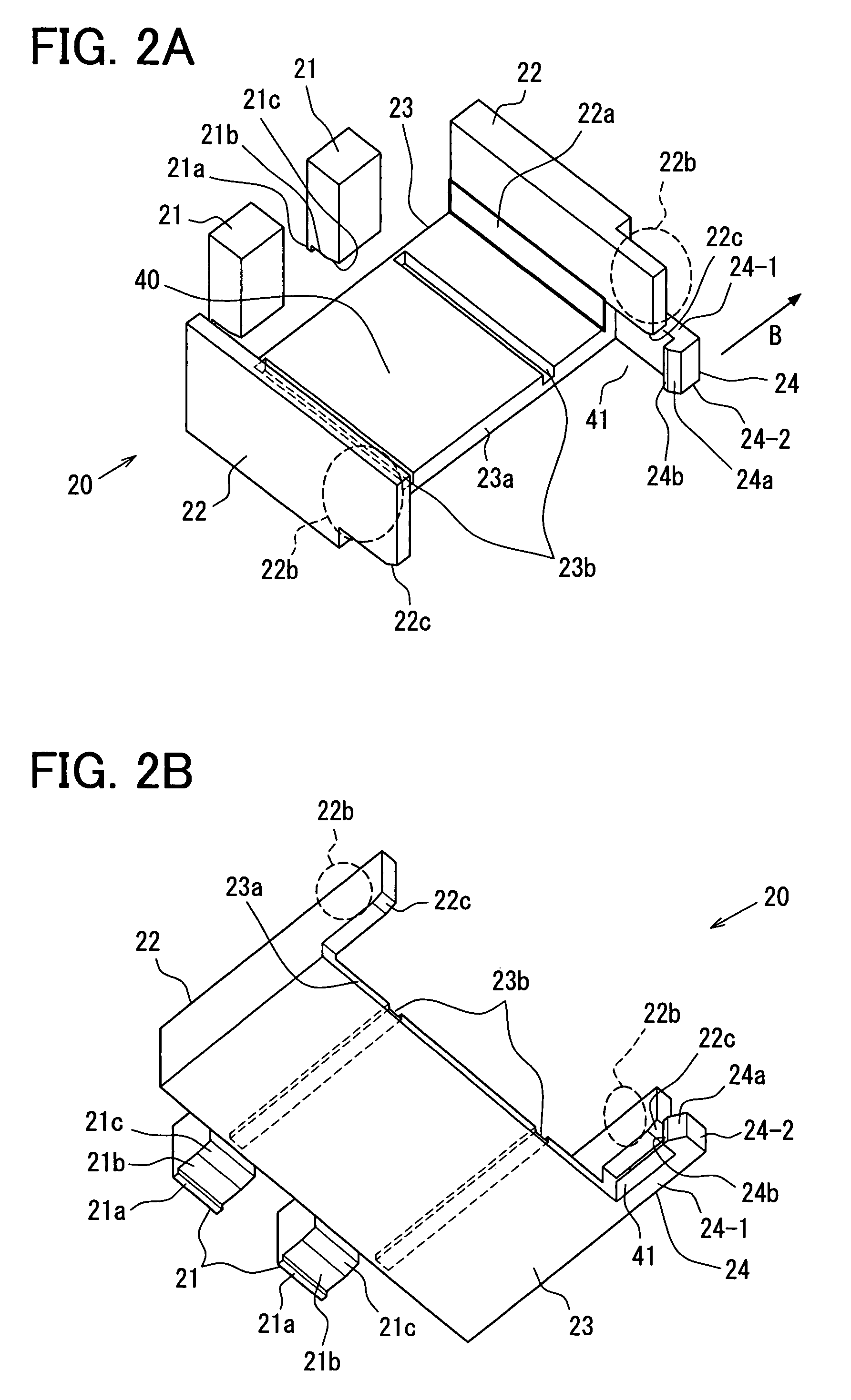
[0029]FIG. 1 is a perspective view showing schematically a state in which an antenna assembly 30 is mounted to an instrument panel-side mounting section 20 and is thereby loaded to an instrument panel 10. (Taking the easiness of seeing the drawing into account, the portion of the instrument panel 10 corresponding to FIG. 10 is cut out in a square shape and is illustrated so that the interior thereof can be seen through). A description will be given below about the configuration of this embodiment.

[0030]A positional relation in the vehicle concerned is the same as that described above in connection with the prior art. That is, the antenna assembly 30 is disposed at a central part in the transverse direction of the vehicle and in a front portion of the vehicle. The relation of the antenna assembly 30 to the vehicle in the longitudinal, transverse and vertical dir...


PUM


Abstract

An antenna mounting assembly includes a stopper, a side wall, a retainer, and a fall-prevention latch on an instrument panel side of the assembly as an integral part of the panel. The fall-prevention latch and a folded part are engaged with each other for holding an antenna body. On the other hand, the antenna body is released from the instrument panel by disengaging the fall-prevention latch from the folded part.

Description

CROSS REFERENCE TO RELATED APPLICATION[0001]This application is based on and claims the benefit of priority of Japanese Patent Application No. 2006-211239 filed on Aug. 2, 2006, the disclosure of which is incorporated herein by reference.FIELD OF THE DISCLOSURE[0002]The present disclosure generally relates to a vehicular antenna structure for mounting and dismounting an antenna assembly on an instrument panel.BACKGROUND INFORMATION[0003]There is a recent tendency to multi-function vehicles possessing not only such basic functions as running, turning and stopping but also a navigation function which utilizes position measurement by a Global Positioning System (GPS) and a vehicle-to-vehicle communication function. This tendency is becoming more and more conspicuous in quick tempo. Besides, importance is being attached to the design in both interior and exterior of a vehicle. Keeping steps with such a tendency, there also is a tendency that various parts and parts assemblies for fulfil...

Claims


Application Information

Patent Timeline
Patent Type & Authority Patents(United States)
IPC IPC(8): H01Q1/32
CPCH01Q1/1207H01Q1/3291H01Q1/3233
Inventor YAMADA, TAKESHI
Owner DENSO CORP
Why Eureka
Try Eureka