Jack for a working implement and method

Inactive Publication Date: 2005-03-31
CURTIS IND INC
View PDF51 Cites 3 Cited by
  • Summary
  • Abstract
  • Description
  • Claims
  • Application Information

AI Technical Summary

Benefits of technology

[0007] The problems of the prior art have been overcome by the present invention, which in one embodiment provides a jack for a mount assembly for snow blades or other working implements or accessories. A plow assembly that optionally includes a lift frame is removably coupled to a mounting frame attached to the vehicle, such as the vehicle chassis. The jack enables proper positioning of the assembly relative to the vehicle or other structure for easy mounting and dismounting thereto.

Problems solved by technology

Conventionally, the lift frame has been permanently mounted to the chassis frame (and therefore not readily removable from the vehicle), and the hydraulic pump used to operate the snow blade was located under the vehicle hood, and were driven using a belt drive driven by the vehicle engine.
However, safety considerations now often dictate that the lift frame be removed when the plow is not in use.
One drawback of conventional snow blade mounts is the difficulty in readily attaching and removing the lift frame assemblies from the vehicle chassis, especially in view of their weight.
This mounting and dismounting is difficult and tedious.

Method used


Image

  • Jack for a working implement and method
  • Jack for a working implement and method
  • Jack for a working implement and method

Examples


second embodiment

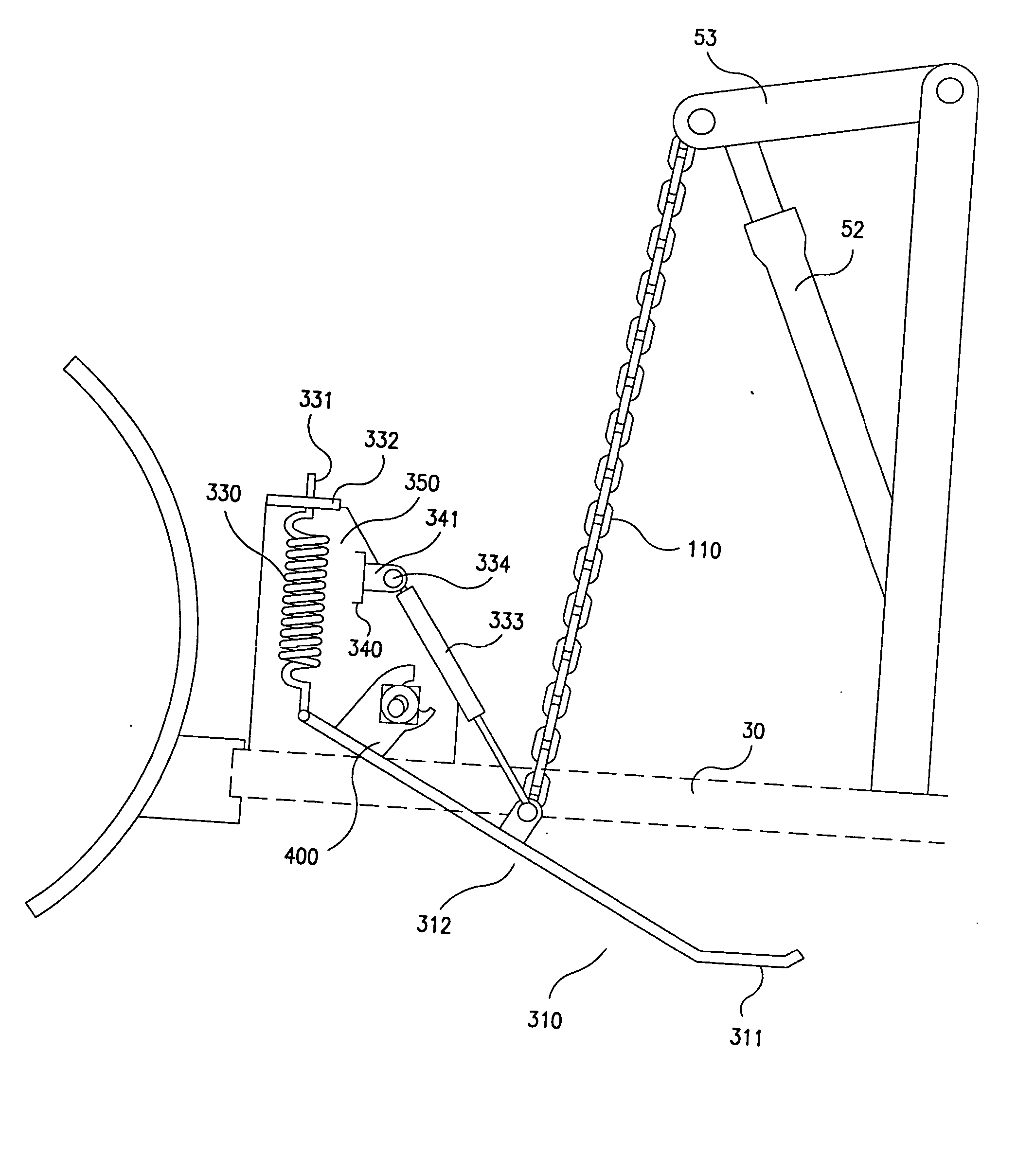
[0043]FIG. 3 illustrates the invention. The jack leg 310 preferably consists of 2 parts; a skid shoe 311 for contacting the ground (or other substrate) and a relatively straight elongated portion 312. Preferably the chain or other linkage 110 is connected to the jack leg 310 in an area between the fulcrum point and the skid shoe 311. Linkage or other means (such as a moment arm) can be used if the chain 110 is connected before the fulcrum point. Locking tab 400 is connected to jack 310 such as by welding.

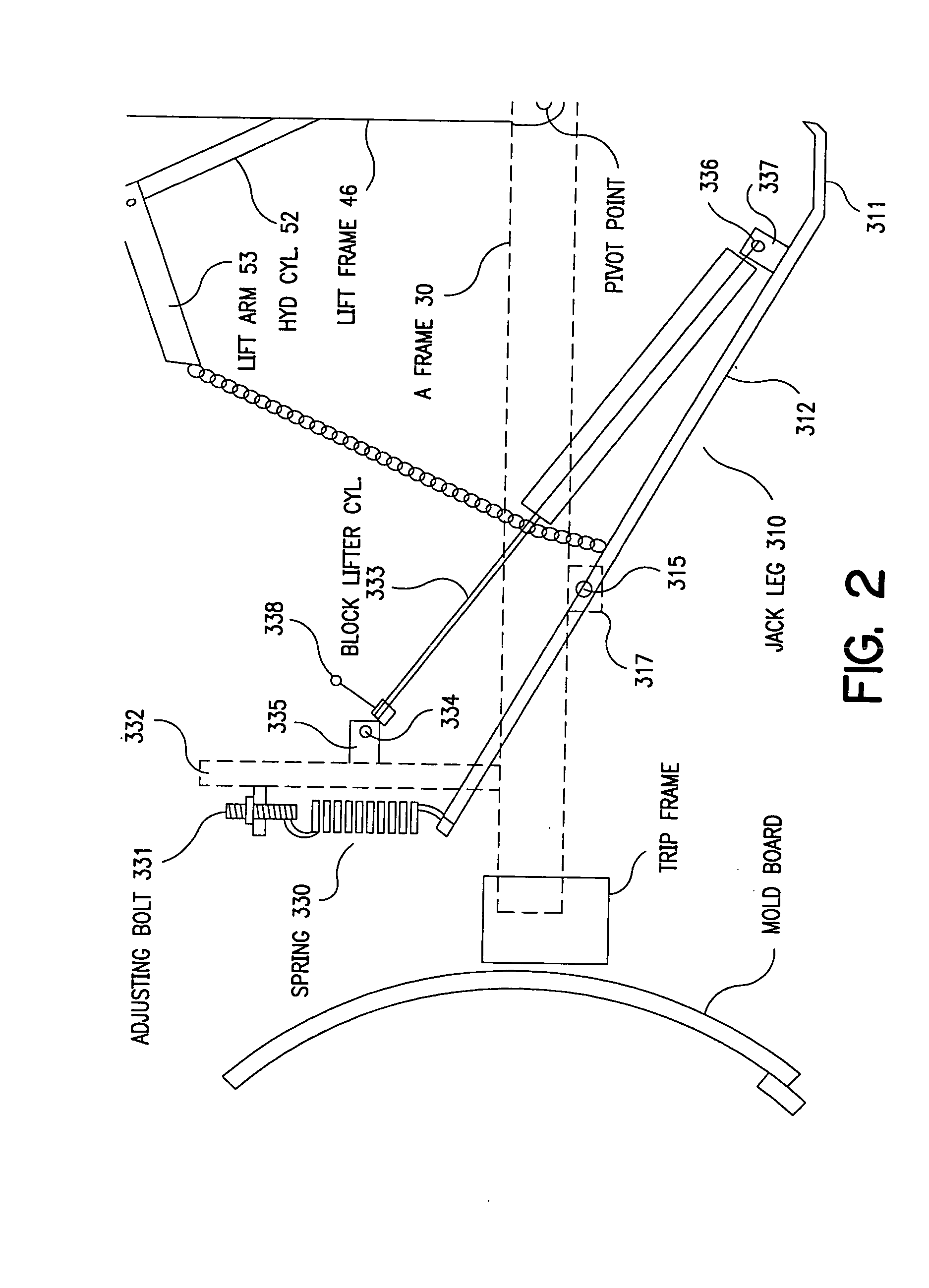
[0044] The jack leg 310 is pivotally connected to the A-frame assembly 30 via jack pivot rod 315 through opposite side gussets 317 (one shown). Additionally, the jack leg is connected to spring 330, which in turn is connected via an adjusting bolt 331, to horizontal bracket 332. This horizontal bracket is attached to a metal shroud 350 such as by welding. Side gusset 341 is connected to the vertical bracket 340 such as by welding. A block lifter cylinder 333 is pivotally attached to...

third embodiment

[0050] In FIG. 6, the invention is shown. The jack leg 310 preferably consists of 2 parts; a skid shoe 311 for contacting the ground (or other substrate) and a relatively straight elongated portion 312. Preferably the chain or other linkage 110 is connected to the jack leg 310 in an area between the fulcrum point and the skid shoe 311. Linkage or other means (such as a moment arm) can be used if the chain 110 is connected before the fulcrum point. The jack leg 310 is pivotally connected to the A-frame assembly 30 via jack pivot rod 315. Jack rod 450 is rigid, preferably made of steel tubing, and at one end is pivotally connected to jack 310 via pivot rod 455. Jack rod 450 has a protrusion 451, appropriately positioned along the length of the rod 450, which comprises a sloped side portion 452, and a relatively straight top portion 453. The jack rod 450 is coupled to the gas cylinder 460 at or near it's opposite end, such as by welding. Jack release handle 480 is connected to the junc...


PUM


Abstract

Jack for raising and lowering a working implement such as hydraulically driven snow blades or other utilitarian accessories. Actuation of the jack allows for proper vertical alignment of the lift assembly for engagement to a vehicle chassis. Once engaged, the jack can be actuated into an inoperative position until the lift assembly is to be removed from the chassis.

Description

[0001] This application is a divisional of U.S. Ser. No. 10 / 368,963 filed Feb. 19, 2003, which claims priority of Provisional Application Ser. No. 60 / 412,347 filed Sep. 20, 2002 and Provisional Application Ser. No. 60 / 434,556 filed Dec. 18, 2002; the disclosures of which are hereby incorporated by reference.BACKGROUND OF THE INVENTION [0002] Conventional snow blade mounts for four wheel drive vehicles such as pick-up trucks and ATV's can weigh several hundred pounds, and generally include a chassis frame that can be permanently fixed to the vehicle chassis, usually behind the vehicle front bumper. A lift frame is then removably coupled to the chassis frame, and the snow blade is then coupled to the front end of the assembly via an A-frame and trip frame assembly. The A-frame with the snow blade attached is typically removable from the vehicle. Conventionally, the lift frame has been permanently mounted to the chassis frame (and therefore not readily removable from the vehicle), and ...

Claims


Application Information

Patent Timeline
IPC IPC(8): E01H1/00E01H5/06
CPCE01H5/066E01H1/00
Inventor CURTIS, MARC D.
Owner CURTIS IND INC
Why Eureka
Try Eureka