Needle roller bearing

a technology needle rollers, which is applied in the direction of needle bearings, roller bearings, mechanical equipment, etc., can solve the problems of affecting the working environment affecting the service life of needle roller bearings, and the inability to provide a central lubrication line, so as to increase the sealing capacity and facilitate the dismounting and replacement of the cage. , the effect of increasing the sealing capacity

Pending Publication Date: 2022-07-07
AB SKF
View PDF5 Cites 0 Cited by
  • Summary
  • Abstract
  • Description
  • Claims
  • Application Information

AI Technical Summary

Benefits of technology

[0017]Further, the inner ring and / or the outer ring may include at least one flange at an axial side thereof to guide the needle rollers. Since the at least one flange usually covers an area that allows a fiber entry into the bearing, the at least one flange also hinders fibers from entering. In addition, the at least one flange may be provided with at least one knurled surface to increase a sealing capacity provided by the at least one flange. Also, the bottom roller bearing may be provided with a cage. The cage may be split so that the cage can be mounted over the inner ring flanges. This allows an easy dismounting and replacement of the cage.

Problems solved by technology

Because of fibers particles, which can be released from the handled textiles, yarns, threads, etc. into the air, the environment, in which these roller bearings work, is rather harsh.
In particular, the fiber particles in the air can easily enter the bearings and can cause bearing blockages and / or bearing failures.
Due to the arrangement of the bearings in the machine, it is often not possible to provide a central lubrication line such that the frequent relubrication needs to be performed manually at each of the bearings in order to replace the used lubricant.
However, the procedure is both work and cost intensive and reduces the production rate.
However, depending on the type of the used bearing and / or whether this bearing has flanges at its axial sides, there may not be enough space to accommodate a sealing unit.
In addition, sealing units increase friction as well as the overall bearing costs.

Method used


Image

  • Needle roller bearing
  • Needle roller bearing

Examples


Embodiment Construction

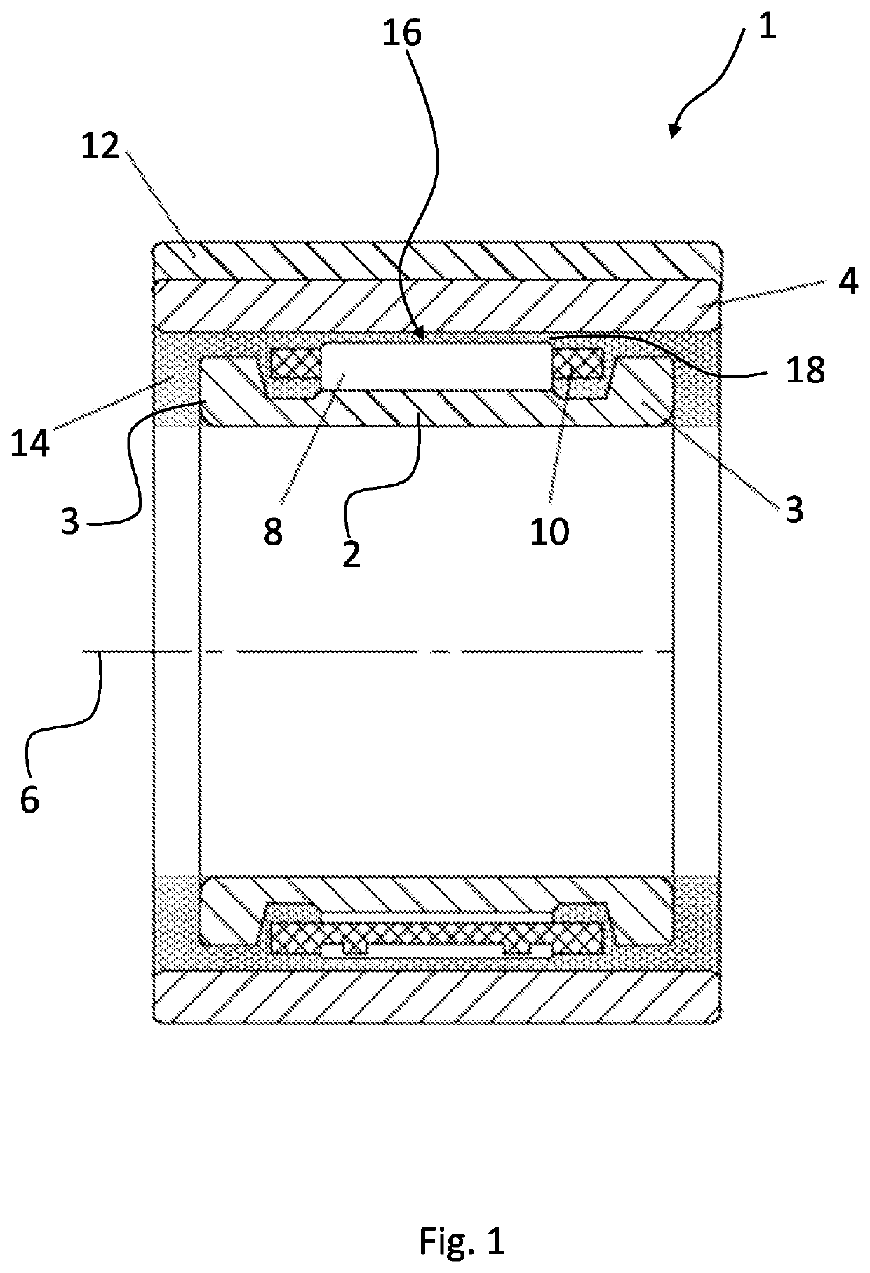
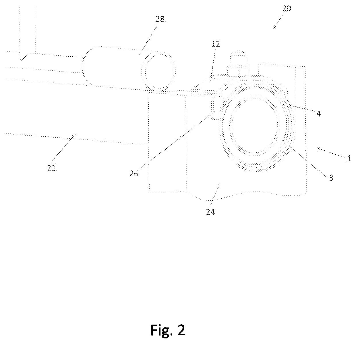
[0023]FIG. 1 shows a cross section of a needle roller bearing 1. The needle roller bearing 1 comprises an inner ring 2 and an outer ring 4. The inner ring 2 and the outer ring 4 are arranged concentrically to each other and in such a way that the inner ring 2 and the outer ring 4 are rotatable relatively to each other around a bearing rotation axis 6. In FIG. 1, the inner ring 2 is mounted as a rotatable inner ring onto a shaft, for example a bottom roller 22 (FIG. 2), whereas the outer ring 4 is fixed. Furthermore, the inner ring 2 has a flange 3 at each axial side.

[0024]The needle roller bearing 1 includes a plurality of needle rollers 8, which are disposed in a rolling chamber being defined between the inner ring 2 and the outer ring 4. The needle rollers 8 are configured to roll on raceways (not referenced) that are provided on both the inner ring 2 and the outer ring 4. Additionally, the needle rollers 8 of the needle roller bearing are held by a cage 10. The cage 10 is configu...


PUM


Abstract

Disclosed is a needle roller bearing, in particular for use in supporting a bottom roller in a spinning machine. The needle roller bearing includes an inner ring and an outer ring which are arranged such that the inner ring and the outer ring are rotatable relatively to each other around a bearing rotation axis. A rolling chamber is defined between the inner ring and the outer ring, in which a plurality of needle rollers are arranged. A solid lubricant is disposed in the rolling chamber of the needle roller bearing.

Description

CROSS-REFERENCE TO RELATED APPLICATIONS[0001]This application claims priority to Chinese Patent Application no. 202110016654.3, filed Jan. 7, 2021, the contents of which is fully incorporated herein by reference.FIELD OF THE INVENTION[0002]The present invention relates to a needle roller bearing. In particular, the present invention relates to a needle roller bearing for use in spinning machines.BACKGROUND OF THE INVENTION[0003]Needle roller bearings are often used in the textile industry in different types of machines. Usually, the used machines include several needle roller bearings at different positions in the machine. Because of fibers particles, which can be released from the handled textiles, yarns, threads, etc. into the air, the environment, in which these roller bearings work, is rather harsh. In particular, the fiber particles in the air can easily enter the bearings and can cause bearing blockages and / or bearing failures.[0004]In order to further reduce the number of bea...

Claims


Application Information

Patent Timeline
Patent Type & Authority Applications(United States)
IPC IPC(8): F16C19/46F16C33/46F16C33/54F16C33/56F16C33/66
CPCF16C19/463F16C33/4605F16C33/546F16C2361/61F16C33/6677F16C33/6696F16C33/565F16C19/46F16C33/76F16C33/583F16C33/6648D01H5/74F16C2340/18
Inventor DU, SHIHAOKETTNER, THOMASMETZ, HARALDDINKEL, SEBASTIAN
Owner AB SKF
Why Eureka
Try Eureka