Rapid ratchet wrench capable of being used in one hand

a ratchet wrench and ratchet head technology, applied in the field of ratchet wrenches capable of being used in one hand, can solve problems such as affecting work efficiency, and achieve the effects of convenient pushing of the ratchet head, convenient use, and good operation

Active Publication Date: 2021-07-22
NINGBO S CHANDE IMPORT&EXPORT CO LTD
View PDF0 Cites 0 Cited by
  • Summary
  • Abstract
  • Description
  • Claims
  • Application Information

AI Technical Summary

Benefits of technology

[0006]Preferably, the said handle is internally provided with an inner hole, the control mechanism is mounted in the inner hole, a through hole is provided at the area where the handle is joined to the wrench head, which connects the inner hole through the sleeve hole, and the control mechanism runs across this through hole. The said control mechanism is mounted in the inner hole that is arranged in the middle part of the handle, which can prevent the control mechanism against unexpected damage, and avoid the interiors of the control mechanism from depositing dust or other objects that may undermine its free movement.
[0007]Preferably, a movable hole connecting through the inner hole is disposed on the side wall of the handle, the said propelling head runs across the movable hole and is arranged outside the handle. When gripping the handle, fingers can easily push the propelling head, which makes it good for operation and allows for the best hand grip.
[0008]Preferably, the said control mechanism comprises a top shaft and a positioning mechanism. The tensioner head is mounted on the top end of the top shaft and its position can be secured by means of the positioning mechanism. This wrench can be used in two states: counterclockwise rotation and clockwise rotation. Throughout the process of one state, two pawls need to be stable. In other words, the tensioner head should remain in a relatively stationary position, and its position can be located by setting the positioning mechanism, so that the wrench is more user-friendly.
[0009]Preferably, the said positioning mechanism is a ratchet retractable mechanism comprising a pressing head, a rotating head, a guide strip and a return spring. The rotating head is joined to the top shaft, the said return spring is nested on the top shaft, with one end against the body of the handle and the other end against the block bar disposed on the top shaft; the said propelling head is provided on the pressing head. When this ratchet retractable mechanism is used, the entire control mechanism can be adjusted by only pushing the propelling head, which features user-friendly and fault-free operation.
[0010]Further, the said guide strip is arranged on the inner wall of the inner sleeve, the inner sleeve is mounted in the inner hole, the front end of the inner sleeve is provided with a hole allowing the top shaft to run across, and the said pressing head and rotating head are inserted in the inner positioning sleeve. The guide strip in the ratchet retractable mechanism is arranged inside the inner sleeve, and the pressing head and rotating head are nested in the inner sleeve. This arrangement can make it easier for the mounting and dismounting of all the components of the ratchet retractable mechanism, and facilitate the mass production, disassembly and repair service of this ratchet wrench.
[0011]Further, a screw hole connecting through the inner hole is disposed on the handle, and a positioning bolt that functions as securing the inner sleeve is mounted in the screw hole. The inner sleeve can be securely fixed in the inner hole by tightening the positioning bolt, so that the inner sleeve can avoid from swaying.

Problems solved by technology

This way of operation doesn't make for the operation of ratchet wrench, leading to compromised working efficiency.

Method used


Image

  • Rapid ratchet wrench capable of being used in one hand
  • Rapid ratchet wrench capable of being used in one hand
  • Rapid ratchet wrench capable of being used in one hand

Examples


Embodiment Construction

[0020]Referring to the accompanying drawings and embodiments, the mode of carrying out the present application will be described in details below, in order to fully understand how this application uses technical means to solve technical problems and achieve technical outcome, and to carry out this application accordingly.

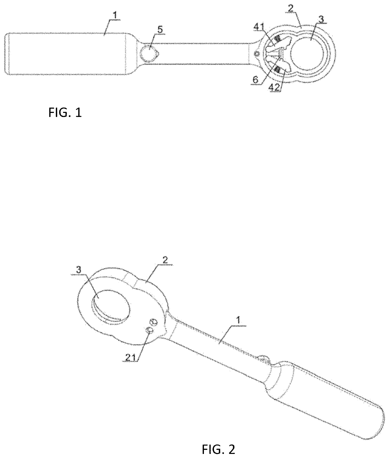
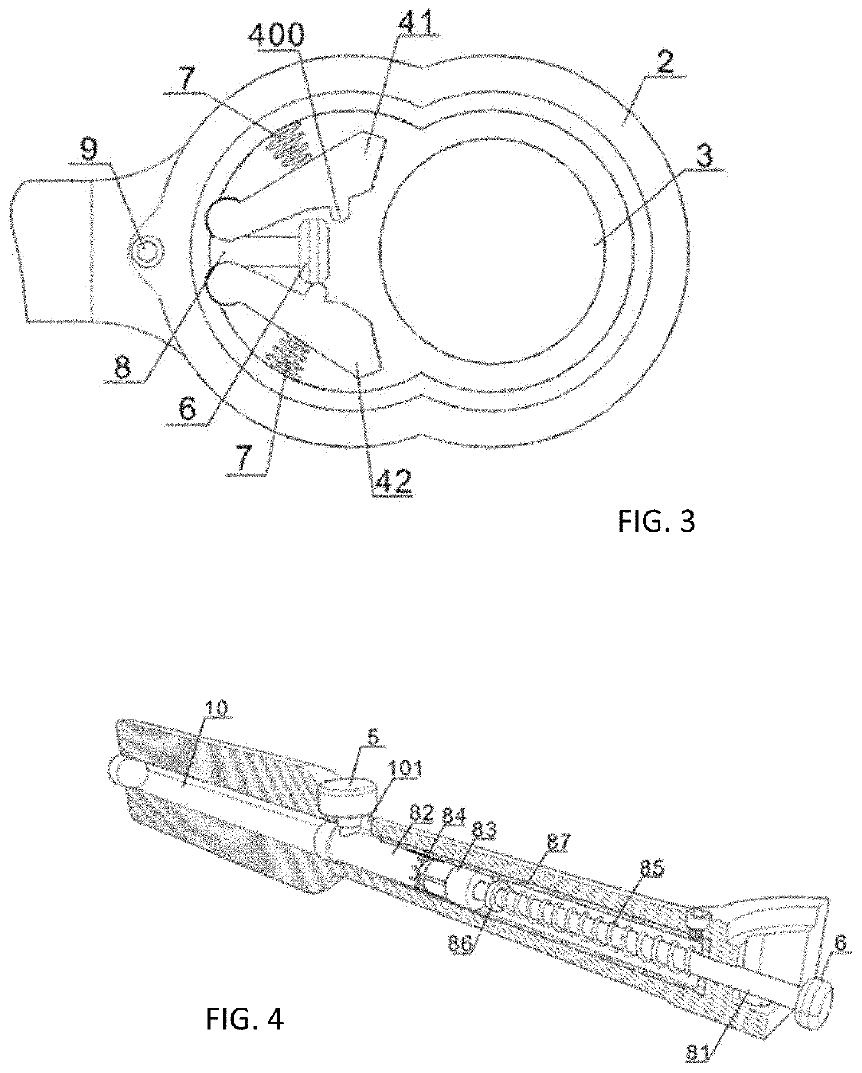
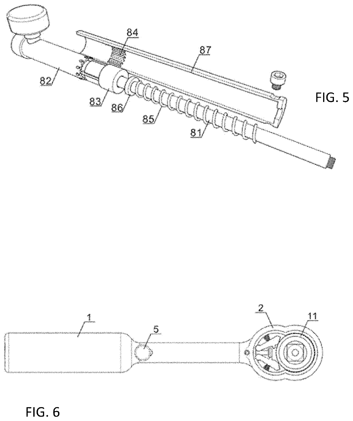
[0021]Referring to FIGS. 1-3 and FIG. 6, the present invention provides an embodiment: the existing ratchet wrench 20 functions as the general body, the wrench head 2 is arranged at the top end of the handle 1, the front face of the wrench head 2 is provided with a groove whose front part is provided with a sleeve hole 3, and the left pawl 41 and the right pawl 42 are arranged at positions close to the handle in the groove. The positioning hole is provided at the rear part of the bottom of the groove, a rotating shaft is arranged the ends of the left and right pawls which are mounted in the positioning hole 21 by the rotating shaft, and the said two pawls can deflec...


PUM


Abstract

A rapid ratchet wrench capable of being used in one hand comprises a handle, a wrench head, pawls, and a tensioner head, wherein the wrench head is arranged at the top end of the handle, and a left pawl and a right pawl are arranged at positions close to the handle in a sleeve hole. The tensioner head is mounted at the top end of a control mechanism, and a propelling head is arranged at the tail end of the control mechanism; and the adjacent sides of the left pawl and the right pawl are respectively provided with a touch head in a staggered manner, the tensioner head can respectively touch one of the touch heads and ejects the corresponding pawl to make same open outwards, and the other touch head is in the working position.

Description

TECHNICAL FIELD[0001]The present invention relates to the technical field of hardware tools and is specifically a rapid ratchet wrench capable of being used in one hand.BACKGROUND ART[0002]Ratchet wrench is a wrench tool that drives the rotating of nut in forward rotation, and makes the pawl slide relative to the nut in reverse rotation with the nut not rotated. In case of ratchet wrenches with two pawls available on the market, a tensioner head is provided between two pawls. When in use, its handle is held in one hand with the tensioner head rotated with the aid of the other hand, so that the tensioner head can respectively push the left or right pawl, until one of the pawls is in the working position. This way of operation doesn't make for the operation of ratchet wrench, leading to compromised working efficiency.SUMMARY OF THE INVENTION[0003]The object of the present invention is to provide a rapid ratchet wrench capable of being used in one hand. User can adjust the working stat...

Claims


Application Information

Patent Timeline
Patent Type & Authority Applications(United States)
IPC IPC(8): B25B13/46
CPCB25B13/46B25B13/463
Inventor WU, WEIJUN
Owner NINGBO S CHANDE IMPORT&EXPORT CO LTD
Why Eureka
Try Eureka