Image forming apparatus controlling a droplet size of a fixing solution

a technology of droplet size and fixing solution, which is applied in the direction of electrographic process apparatus, instruments, optics, etc., can solve the problems of image deterioration, inability to fix the toner image, and reduced temperature of the toner image, so as to reduce the amount of heat energy and avoid curling or wrinkles

Inactive Publication Date: 2010-06-29
SHARP KK
View PDF14 Cites 7 Cited by
  • Summary
  • Abstract
  • Description
  • Claims
  • Application Information

AI Technical Summary

Benefits of technology

[0010]It is an object of the invention to provide an image forming apparatus involving wet fixing that causes no flow or aggregation of toner and eventually no disturbance of toner image as a result of application of a fixing solution, generates no curling or wrinkles in a recording medium, can reduce an amount of heat energy and eventually power consumption and consumption of the fixing solution, takes a relatively short time to fix even a multicolored toner image, and can fix toner with large adhesion on a recording medium through which the fixing solution hardly permeates.

Problems solved by technology

However, in this image forming apparatus, the recording medium is not heated, and therefore when a toner image is brought in contact with the recording medium for transfer and fixing, the temperature of the toner image is reduced, so that the toner image may not be fixed or image deterioration due to offset or the like may occur.
With the image forming apparatus of JP-A 2004-151626, the adhesion of the toner image to the recording medium is improved, but since not only the toner image, but also the recording medium is heated, a heating section with a large heat capacity is required, thereby increasing power consumption and resulting in a current situation in which the heating section consumes at least a half of the total power consumed in the image forming apparatus.
Furthermore, in the heat fixing, as described above, the heating section is used inside the apparatus, and the inside of the apparatus reaches a high temperature, so that it is necessary to increase the heat resistance of the components thereof, thereby increasing the material cost.
Furthermore, the heat fixing has a problem in that fixing of a multicolored toner image onto a recording medium takes more time than fixing a monochromatic toner image.
However, an unfixed toner image is merely an aggregate in which toner particles gather without being physically or chemically bonded at room temperature.
As a result, a blur is generated in the image edge after fixing, and non-uniformity occurs in a half tone portion that should be uniform, so that high definition images cannot be achieved.
It is natural that even when heating is performed after flow or aggregation of toner particles occurs, the original state cannot be recovered.
However, when the fixing solution is applied only to the image portion in the recording medium, expansion and contraction occurs in the image portion, and does not occur in the non-image portion, so that wrinkles originating from the image portion are inevitably generated.
In particular, when recording paper made from paper fiber with water is used as the recording medium, this tendency is significant.
However, the minimum amount is very small, so that it is difficult to weigh the minimum amount accurately.
Moreover, when the fixing solution is applied only to the image portion, toner attached to the non-image portion surrounding the image portion, for example, due to fogging remains on the recording medium without being fixed, so that the unfixed toner may soil hands or clothing.
However, a large amount of fixing solution is necessary in order to enhance the adhesion between the toner image and the recording medium and between the toner particles, in the case where heat is not supplied for transfer and fixing and there is no particular measure for that, as in JP-A 10-63121.
When a large amount of fixing solution is used, wrinkles or curling is inevitably generated in the recording medium.
Moreover, it is necessary to often supply the fixing solution or necessary to provide a large capacity tank for storing the fixing solution, resulting in poor maintainability or increase in the size of the apparatus.
Furthermore, when toner images on resin recording media such as sheets for over heat projectors (hereinafter, referred to as “OHP sheets”), recording media having a resin layer on its surface or other media through which the fixing solution hardly permeates are fixed with the conventional wet fixing type image forming apparatus, the adhesion of toner becomes insufficient, and toner images may partially peel off.

Method used


Image

  • Image forming apparatus controlling a droplet size of a fixing solution
  • Image forming apparatus controlling a droplet size of a fixing solution
  • Image forming apparatus controlling a droplet size of a fixing solution

Examples


first embodiment

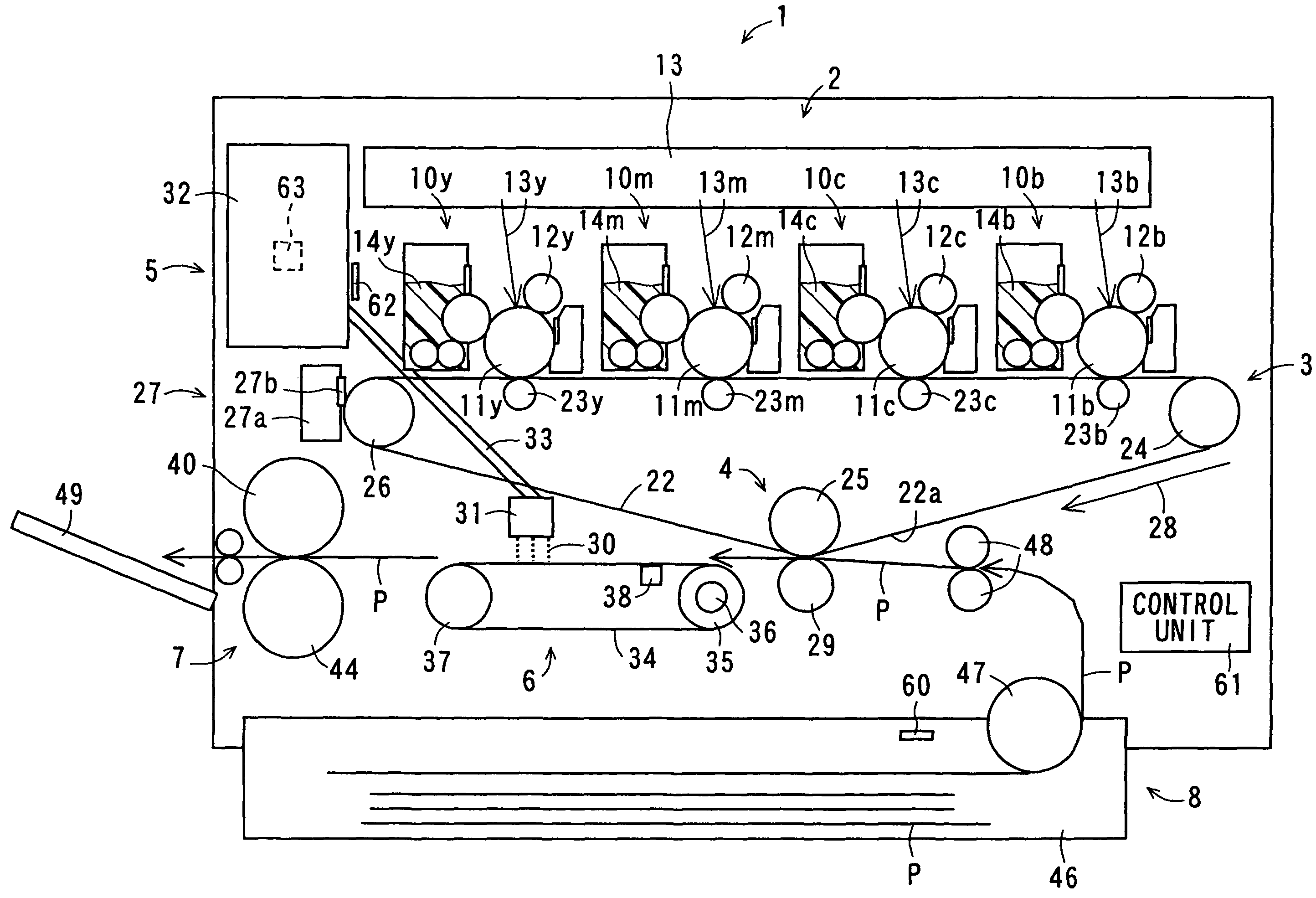
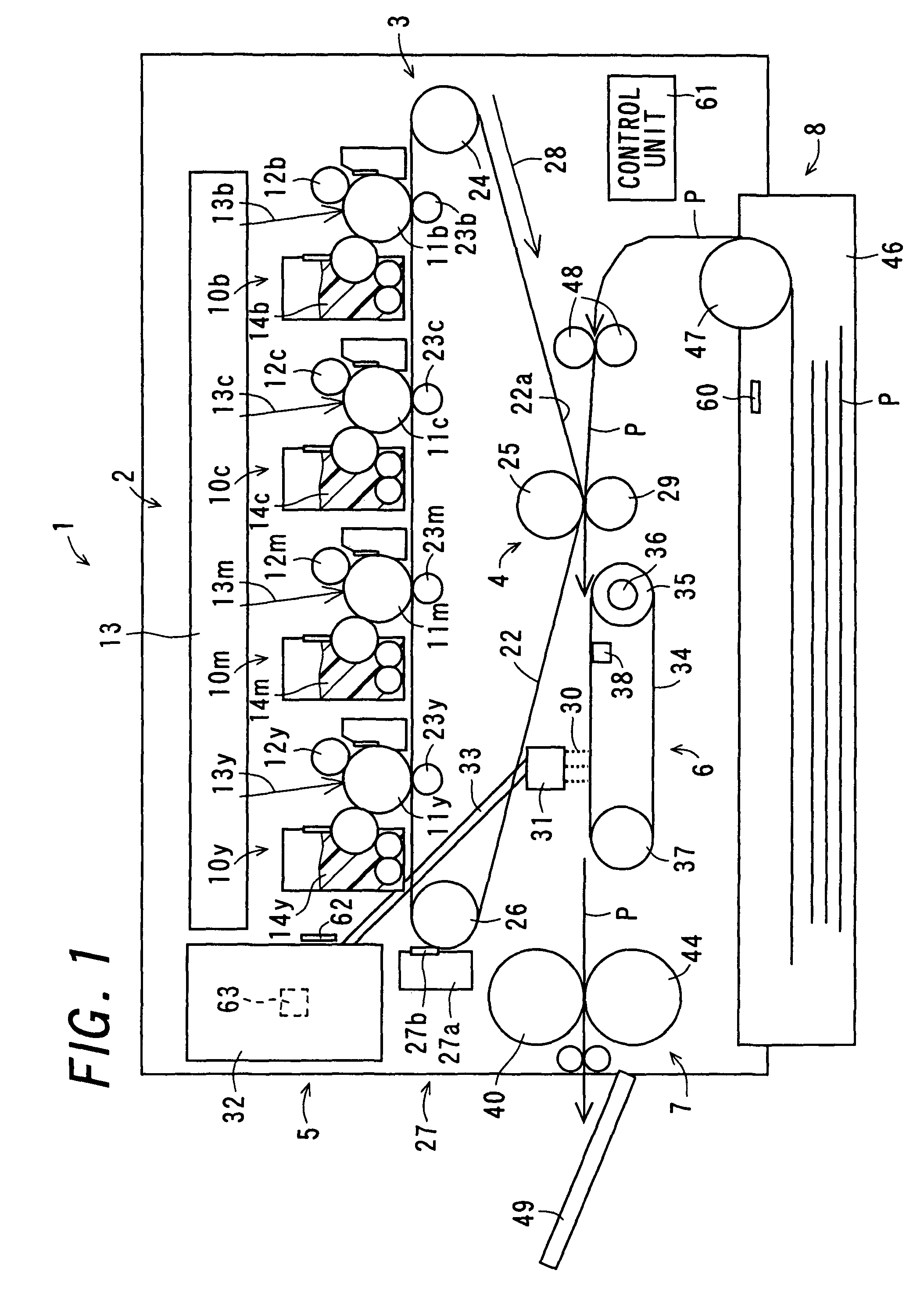
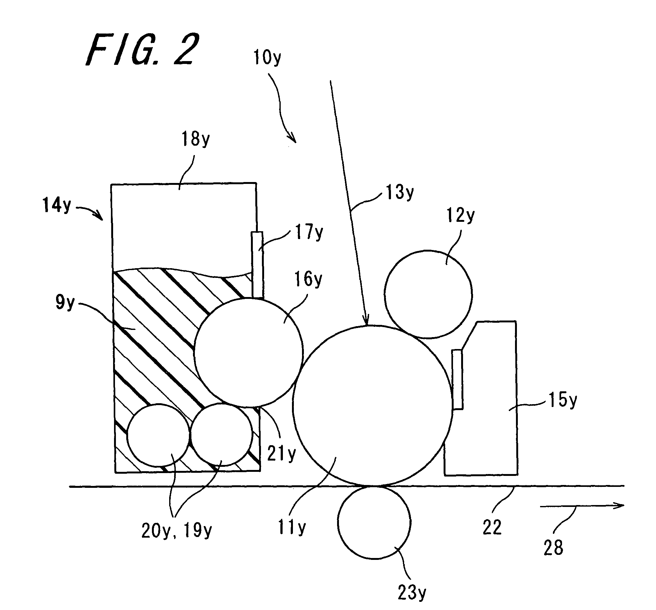
[0049]FIG. 1 is a cross-sectional view schematically showing the configuration of an image forming apparatus 1 according to the invention. FIG. 2 is a cross-sectional view showing an enlarged configuration of the main portion (a toner image forming section 2, which will be described later) of the image forming apparatus 1 shown in FIG. 1. FIG. 3 is a cross-sectional view showing an enlarged configuration of the main portions (a transferring section 4, a part of fixing solution applying section 5, a transporting section 6, and a fixing section 7, which will be described later) of the image forming apparatus 1 shown in FIG. 1. FIG. 4 is a cross-sectional view schematically showing the configuration of a fixing roller 40, which will be described later. The image forming apparatus 1 is an electrophotographic image forming apparatus with a tandem structure in which toner images in four colors, yellow, magenta, cyan, and black are sequentially transferred while being superimposed one on a...

second embodiment

[0095]FIG. 5 is a cross-sectional view schematically showing the configuration of the main portions of an image forming apparatus 50 according to the invention. The image forming apparatus 50 is similar to the image forming apparatus 1. The components corresponding between these image forming apparatuses are given the same reference numbers or not shown in the drawing, and a description thereof is not repeated. The image forming apparatus 50 is characterized by a comprising transporting section 51 and a fixing section 52, instead of the transporting section 6 and the fixing section 7 in the image forming apparatus 1. Also, the image forming apparatus 50 is characterized by further comprising a fixing solution warming section 62a inside the fixing solution storage tank 32 of the fixing solution applying section 5.

[0096]The fixing solution warming section 62a and the temperature sensor 63 are provided inside the fixing solution storage tank 32 in the fixing solution applying section 5...


PUM


Abstract

An image forming apparatus includes a toner image forming section, an intermediate transferring section, a transferring section, a fixing solution applying section, a transporting section, a fixing section, and a recording medium feeding section. In the image forming apparatus, the fixing solution applying section includes a droplet supplying section, a recording medium detecting section, and a control unit, wherein the recording medium is heated before or at the same time when the fixing solution is applied to the recording medium by the fixing solution applying section, and a size of droplets of the fixing solution supplied to the recording medium is controlled based on the type of the recording medium.

Description

CROSS-REFERENCE TO RELATED APPLICATION[0001]This application claims priority to Japanese Patent Application No. 2006-44457, which was filed on Feb. 21, 2006, the contents of which, are incorporated herein by reference, in their entirety.BACKGROUND OF THE INVENTION[0002]1. Field of the Invention[0003]The present invention relates to an image forming apparatus.[0004]2. Description of the Related Art[0005]An electrophotographic method-based image forming apparatus finds wide application in copying machines, printers, facsimile machines, or the like equipment. In general, image formation is accomplished in the following manner. Firstly, there is prepared a photoreceptor having a photosensitive layer containing a photoconductive substance formed on the surface thereof. After the surface of the photoreceptor is electrically charged uniformly, an electrostatic latent image corresponding to image data is formed thereon through a few different image-forming process steps. The electrostatic l...

Claims


Application Information

Patent Timeline
Patent Type & Authority Patents(United States)
IPC IPC(8): G03G15/20
CPCG03G15/657G03G15/2064
Inventor TANAKA, ATSUSHIASAKURA, KENJI
Owner SHARP KK
Why Eureka
Try Eureka