
Composite component and method for producing a composite component

a composite component and composite technology, applied in the field of composite components, can solve the problems of weight and cost advantages, achieve the effects of improving mechanical load tolerance of composite components, increasing the rigidity of composite components, and improving weight and cost advantages

Inactive Publication Date: 2010-07-13
FAURECIA INNENRAUM SYST
View PDF5 Cites 3 Cited by
  • Summary
  • Abstract
  • Description
  • Claims
  • Application Information

AI Technical Summary

Benefits of technology

This solution results in weight and cost advantages, improved mechanical load tolerance, and enhanced crash safety, while maintaining or improving acoustics and comfort in vehicle applications.

Problems solved by technology

In particular, less metal is required for achieving a certain rigidity of the composite component, resulting in weight and cost advantages.

Method used


Image

  • Composite component and method for producing a composite component
  • Composite component and method for producing a composite component
  • Composite component and method for producing a composite component

Examples


Embodiment Construction

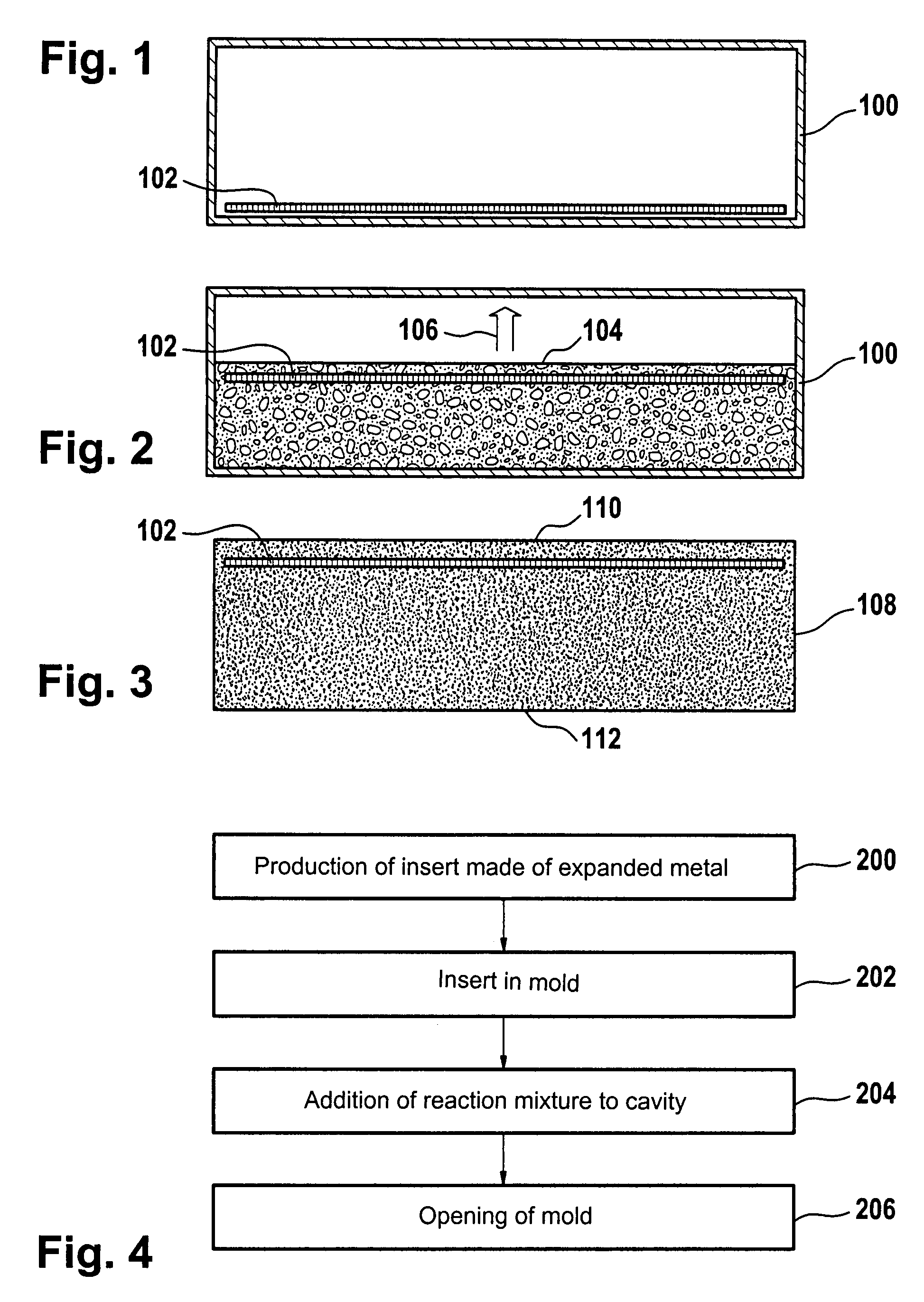
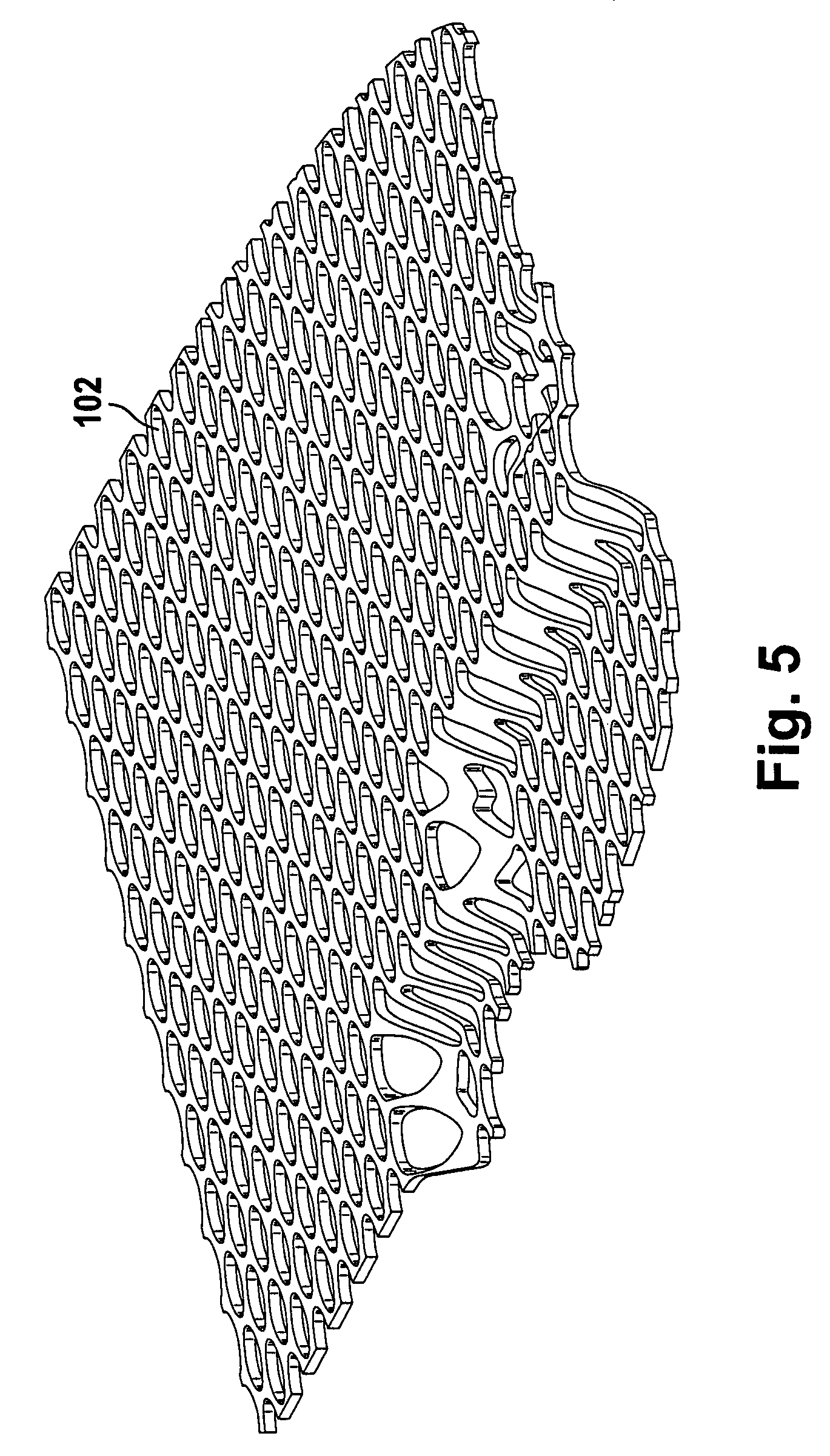
[0027]FIG. 1 shows a mold 100 with an insert 102 made of expanded metal that is placed in the mold 100. In the embodiment illustrated here, the insert 102 is placed on the bottom of the mold 100. The insert 102 is not fastened in the mold 100, but is instead placed loosely in the mold 100.

[0028]FIG. 2 shows the mold 100 after a foaming reaction mixture 104 has been poured into the cavity formed by the mold 100. During the reaction, the foaming reaction mixture 104 forms a homogeneous bond with the insert 102 and moves the insert 102 from the bottom of the mold 100 in the direction of the arrow 106 to the side of the mold 100 opposite the bottom.

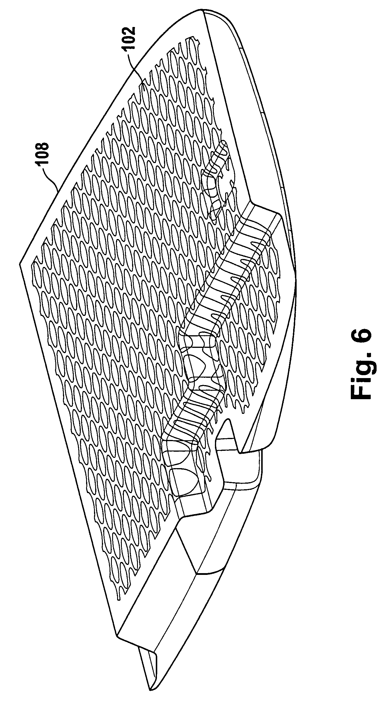
[0029]After opening the mold 100, the composite component 108 with the insert 102 is obtained, which insert is disposed such that it abuts a surface 110 of the composite component 108, as is shown in FIG. 3.

[0030]The reaction mixture 104 poured into the mold 100 preferably comprises polymers, which are mixed with reactive components, such as ...


PUM

PropertyMeasurementUnit
widthaaaaaaaaaa
lengthaaaaaaaaaa
widthaaaaaaaaaa

Abstract

The invention relates to a composite component comprising an insert made of expanded metal surrounded by foamed material, particularly a steering column collision protection element.

Description

BACKGROUND[0001]The invention relates to a composite component, particularly an impact absorber, a motor vehicle body component, a motor vehicle inside molding component, a structural component, such as a closure cap, as well as a vehicle seat, and to a method for producing a composite component.[0002]From DE 101 61 155 A1, a composite component made of polyurethane comprising an insert is known. The insert is an object, which can be included entirely or partially in the fiber-reinforced polyurethane layer by foaming. The inserts are made of polymer and / or metal, such as steel, copper, zinc, aluminum or alloys thereof.SUMMARY OF THE INVENTION[0003]In contrast, it is the object of the invention to create an improved composite component, particularly an impact absorber, a steering column collision protection element, a motor vehicle body component, a motor vehicle inside molding component, a structural components such as a closure cap, as well as a vehicle seat, and to create a method...

Claims


Application Information

Patent Timeline
Patent Type & Authority Patents(United States)
IPC IPC(8): B60R21/05B32B5/18
CPCB29C44/1266B29C44/1285B29C70/70B32B3/04B32B3/266B32B5/18B32B15/02B32B15/046B32B15/18B32B15/20B60R21/04B60R21/05F16F1/371F16F7/00F16F7/12B29L2031/771B32B2266/0278B32B2307/56B32B2419/00B32B2605/08F16F2224/0266F16F2234/06Y10T428/31605Y10T428/31678
Inventor FREESTONE, MARTIN
Owner FAURECIA INNENRAUM SYST
Learn More