Unlock instant, AI-driven research and patent intelligence for your innovation.
Printhead with an optical sensor for receiving print data
What is Al technical title?
Al technical title is built by PatSnap Al team. It summarizes the technical point description of the patent document.
a printhead and optical sensor technology, applied in the field of mobile devices incorporating printers, can solve the problems of significant noise generated by nozzle actuation signals, and achieve the effect of improving contact friction
Inactive Publication Date: 2010-07-13
ZAMTEC +1
View PDF24 Cites 7 Cited by
Summary
Abstract
Description
Claims
Application Information
AI Technical Summary
This helps you quickly interpret patents by identifying the three key elements:
Problems solved by technology
Method used
Benefits of technology
Benefits of technology
[0016]Inkjet printhead IC's will typically receive print data as well as nozzle actuation power from a TAB film. However, with large numbers of nozzles and high nozzle firing rates, the nozzle actuation signals can generate a significant amount of noise which can interfere with the print data signal. To provide the printhead with a ‘cleaner’ print data signal, it can be transmitted via an optical link to a sensor on directly on the printhead IC. By pulsing a beacon in the appropriate spectrum, the optical sensor receives the signal free of any electrical noise due to the firing pulses.
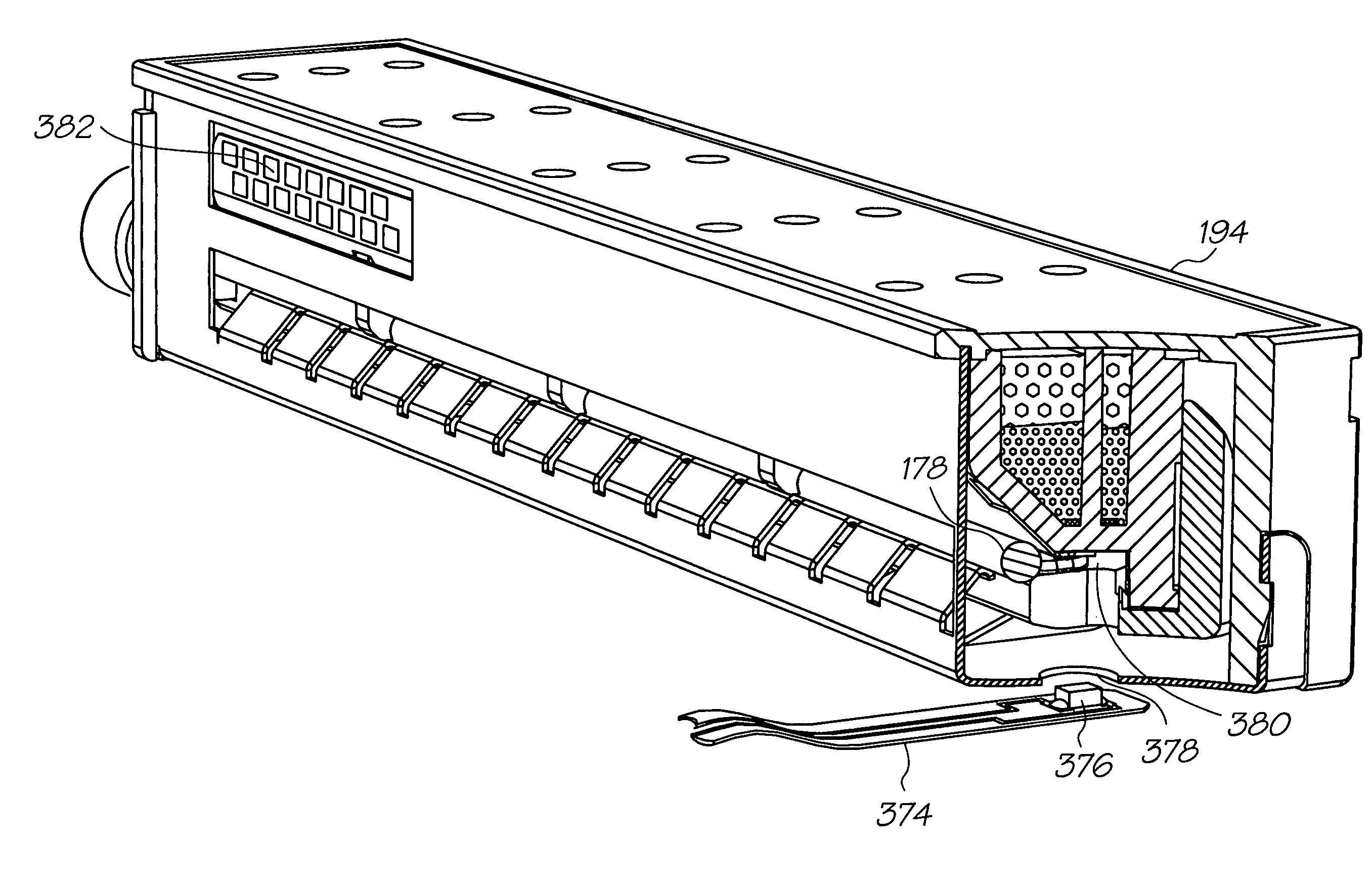
[0027](b) a capping mechanism including a capper moveable between a capping position in which the capper is urged into a capping relationship with the printhead, and an uncapped position in which the printhead is able to print onto the media substrate, wherein in the uncapped position the capper is displaced away from the printhead; and,(c) a force transfer mechanism connected to the capper and configured such that a force provided by an edge of the media substrate as it moves relative to the feed path is transferred to the capper by the force transfer mechanism, thereby to at least commence movement of the capper from the capped position to the uncapped position prior to the media substrate reaching the capper.
[0030]Optionally a mobile telecommunications device further comprising a drive shaft with a media engagement surface for enhanced contact friction with the media substrate.
Problems solved by technology
However, with large numbers of nozzles and high nozzle firing rates, the nozzle actuation signals can generate a significant amount of noise which can interfere with the print data signal.
Method used
Image
Click on the blue label to locate the original text in one second.
Reading with bidirectional positioning of images and text.
Examples
example tag
Structure
[0473]A wide range of different tag structures (as described in the assignee's various cross-referenced Netpage applications) can be used. The preferred tag will now be described in detail.
[0474]FIG. 77 shows the structure of a complete tag 1400. Each of the four black circles 1402 is a target. The tag 1400, and the overall pattern, has four-fold rotational symmetry at the physical level. Each square region 1404 represents a symbol, and each symbol represents four bits of information.
[0475]FIG. 78 shows the structure of a symbol. It contains four macrodots 1406, each of which represents the value of one bit by its presence (one) or absence (zero). The macrodot spacing is specified by the parameter s throughout this document. It has a nominal value of 143 μm, based on 9 dots printed at a pitch of 1600 dots per inch. However, it is allowed to vary by ±10% according to the capabilities of the device used to produce the pattern.
[0476]FIG. 79 shows an array of nine adjacent symb...
PUM
Abstract
A printhead for an inkjet printer with a print engine controller for operatively controlling the printhead, the printhead comprising: an array of nozzles for ejecting ink; print data circuitry for providing the nozzles with print data; and, an optical sensor for optically receiving the print data from a beacon operated by the print engine controller.
Description
FIELD OF INVENTION[0001]The present invention relates to a mobile device incorporating a printer. The invention has primarily been designed for use in a mobile telecommunications device (i.e. a mobile phone) that incorporates a printer, and will be described with reference to such an application. However, it will be appreciated by those skilled in the art that the invention can be used with other types of portable device, or even non-portable devices.COPENDING APPLICATIONS[0002]The following applications have been filed by the Applicant simultaneously with the present application:[0003]11 / 124,15811 / 124,19611 / 124,19911 / 124,16211 / 124,20211 / 124,19711 / 124,15411 / 124,1987,284,92111 / 124,15111 / 124,16011 / 124,19211 / 124,17511 / 124,16311 / 124,14911 / 124,15211 / 124,17311 / 124,1557,236,27111 / 124,17411 / 124,16411 / 124,20011 / 124,19511 / 124,16611 / 124,15011 / 124,17211 / 124,16511 / 124,18611 / 124,18511 / 124,18411 / 124,18211 / 124,20111 / 124,17111 / 124,18111 / 124,16111 / 124,15611 / 124,19111 / 124,15911 / 124,17611 / 124,18811 / 124...
Claims
Application Information
Patent Timeline
Application Date:The date an application was filed.
Publication Date:The date a patent or application was officially published.
First Publication Date:The earliest publication date of a patent with the same application number.
Issue Date:Publication date of the patent grant document.
PCT Entry Date:The Entry date of PCT National Phase.
Estimated Expiry Date:The statutory expiry date of a patent right according to the Patent Law, and it is the longest term of protection that the patent right can achieve without the termination of the patent right due to other reasons(Term extension factor has been taken into account ).
Invalid Date:Actual expiry date is based on effective date or publication date of legal transaction data of invalid patent.

