Passive optical network loss test apparatus and method of use thereof

a test apparatus and optical network technology, applied in the field of passive optical network test apparatus, can solve the problems of multiple faults, complicated use, and high cost achieve the effects of improving the reliability of the test apparatus, improving the accuracy of the test, and improving the reliability of the tes

Active Publication Date: 2010-07-13
ANRITSU CORP
View PDF21 Cites 53 Cited by
  • Summary
  • Abstract
  • Description
  • Claims
  • Application Information

AI Technical Summary

Problems solved by technology

However, such apparatus are often expensive, complicated to use, and require careful reference measurement to be carried out.
However, when systems that are expected to communicate fail, there are multiple possible locations and different types of faults that can be considered as causes of the failure.
For example, a communication can be interrupted because either the sending or the receiving apparatus has failed, because the transmission medium has failed, or because there is a flaw relating to the communication protocols that are being employed.
In fact, there can be multiple faults at one time.
Testing all of the possibilities to identify and correct a communication system failure can easily become a difficult, time-consuming, and costly matter, given the divergent kinds of tests and test apparatus that may be required.

Method used


Image

  • Passive optical network loss test apparatus and method of use thereof
  • Passive optical network loss test apparatus and method of use thereof
  • Passive optical network loss test apparatus and method of use thereof

Examples


second embodiment

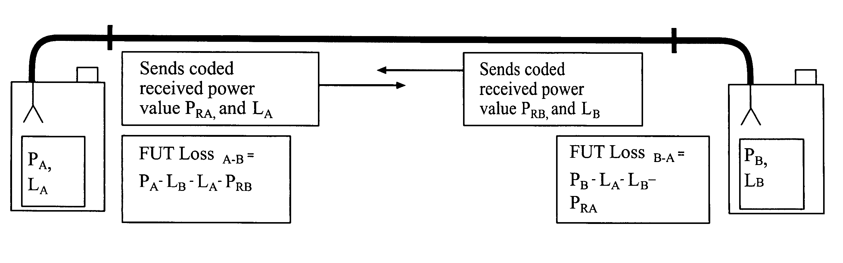
[0188]We now describe another embodiment of the Bidirectional EZTest. The comments made previously about the one button functionality of the Bidirectional EZTest and the overview of the testing procedure apply in this embodiment as well.

[0189]User Selection of Test Configuration

[0190]The user selects from a menu a required number of different wavelengths at which the loss test should be done. The user can define which tests are to be included in the Bidirectional EZTest, (for example Loss, ORL, and any other tests that are available to be conducted by the unit), by interacting with a menu displayed on the apparatus, for example as a Graphical User Interface (“GUI”).

[0191]There is no need to modulate, transmit and demodulate wavelength information between a transmitting unit and a receiving unit because a standard sequence of wavelengths may be employed, in which the wavelength sequence is selected and determined before the test is run. In the instruments and methods described herein...


PUM


Abstract

An apparatus and methods for testing a passive optical network with regard to fiber connectivity and attenuation losses, and with regard to the proper operation of packet-based communication protocols thereon.

Description

CROSS-REFERENCE TO RELATED APPLICATIONS[0001]This application claims priority to and the benefit of co-pending U.S. provisional patent application Ser. No. 60 / 659,837, filed Mar. 7, 2005, which application is incorporated herein by reference in its entirety. This application is related to copending U.S. utility patent application Ser. No. 10 / 847,790, entitled “Improved Accuracy Automated Optical Time Domain Reflectometry Optical Return Loss Measurements Using A “Smart” Test Fiber Module,” filed May 18, 2004, which application is incorporated herein by reference in its entirety, and which application is assigned to the assignee of the present application.FIELD OF THE INVENTION[0002]The invention relates to passive optical network test apparatus in general and particularly to a passive optical network test apparatus that allows testing while the network remains operational.BACKGROUND OF THE INVENTION[0003]Passive Optical Networks (“PON”) are used for communication purposes because the...

Claims


Application Information

Patent Timeline
Patent Type & Authority Patents(United States)
IPC IPC(8): H04B10/08
CPCH04B10/077H04B10/07955H04L12/2697H04L43/0829H04L43/50
Inventor OFALT, MARTIN MATTHEWSINS, HOWARD D.PANASYUK, SERGEYPEDERSEN, LARS D.
Owner ANRITSU CORP
Why Eureka
Try Eureka