

Fibre optic cable subunit assemblies
A technology for fiber optic components and fiber optic cables, which can be used in optical components, optics, light guides, etc., and can solve problems such as increased labor costs and disturbances.
- Summary
- Abstract
- Description
- Claims
- Application Information
AI Technical Summary
Problems solved by technology
Method used
Image

Examples
example 1
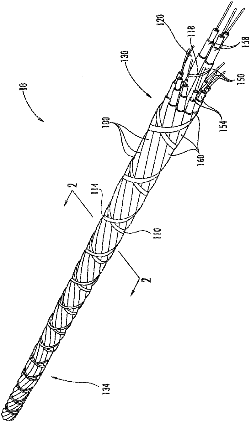
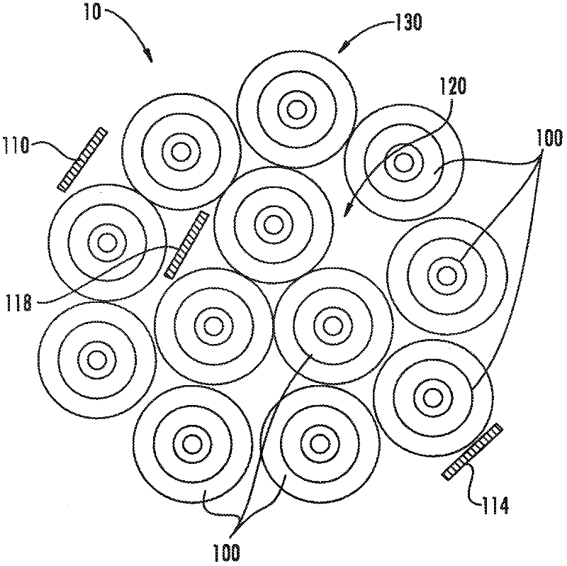
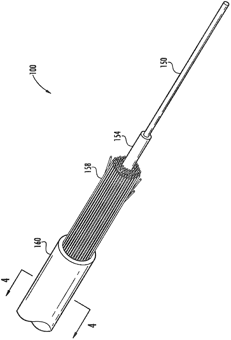
[0038] Figure 1 to Figure 2 The fiber optic assembly 10 illustrated in FIG. 1 is formed of twelve flame retardant fiber optic subunit cables 100 . The subunit cable 100 is a single fiber optic cable with SZ twisted together. The fiber optic assembly 10 has minimal bends so that it can fold up on itself ( Figure 5 ), and have a tensile strength of at least 300 lbs. A pair of outer wraps 110 , 114 made of polyester are twisted in reverse helical shape around the outer layers 130 of the nine subunit cables 100 . The inner wrap 118 is wound helically around the inner layers 120 of the three inner subunit cables 100 . Each subunit cable 100 has a diameter of 2.9 mm. The cable diameter CD is 11.1 mm. Fiber optic assembly 10 has no outer jacket or central strength member. The tensile rating for each subunit fiber optic cable is 50 lbs. The fiber safe stress for the inner three subunit cables 100 is 200 kpsi and for the outer nine subunit cables 100 is 100 kpsi. The higher t...
example 2
[0046] Figure 8 and Figure 9 The fiber optic assembly 200 illustrated in FIG. 2 is formed from twelve flame retardant fiber optic subunit cables 300 . Subunit cables 300 are SZ twisted together and have ClearCurve TM Single-fiber cables with single-mode bend-insensitive fibers. A pair of outer wraps 310 , 314 made of polyester are twisted in reverse helical shape around the outer layers 330 of the nine subunit cables 300 . Each subunit cable 300 has an outer diameter of 1.65 mm. The average cable diameter CD is about 6 mm. Fiber optic assembly 200 has no outer jacket or central strength member. The maximum short-term tensile load for each subunit fiber optic cable 300 is 150 Newtons.
[0047] Figure 10 is a perspective view of a portion of a fiber optic assembly 600 or bundled optical cable according to a third embodiment of the present invention. Figure 11 for fiber optic assembly 600 along the Figure 10 Cross-sectional view of line 11-11 in. Fiber optic assemb...
example 3
[0051] Figure 10 and Figure 11 The fiber optic assembly 600 illustrated in is formed from six flame retardant fiber optic subunit cables 300 . Subunit cables 300 are SZ twisted together and have ClearCurve TM Single-fiber cables with single-mode bend-insensitive fibers. A pair of outer wraps 610 , 614 made of polyester are twisted in reverse helical shape around the outer layer 630 of the nine subunit cables 300 . Each subunit cable 300 has a diameter of 1.65 mm. The cable diameter CD is 4.8mm. Fiber optic assembly 600 has no outer jacket or central strength member. The maximum short-term tensile load for each subunit fiber optic cable 300 is 150 Newtons.
[0052] Table 1 describes the ClearCurve using subunit cable 300 TM single mode fiber, Figure 10 Attenuation data for cable assembly 600 at a wavelength of 1550 nm as a function of the number of wraps in a mandrel wrap test using a 15 mm diameter mandrel.
[0053] Table 1 - 15mm Mandrel Wrap Delta Attenuation at ...
PUM
| Property | Measurement | Unit |
|---|---|---|
| The average diameter | aaaaa | aaaaa |
| The average diameter | aaaaa | aaaaa |
| The average diameter | aaaaa | aaaaa |
Abstract
Description
Claims
Application Information