Circulating hot tube type radiator

A radiator and heat exchange tube technology, applied in the field of heat dissipation of electronic devices, can solve the problems of low production efficiency, high requirements on the accuracy of the outer diameter of the heat pipe, and high cost and price of the heat pipe

Inactive Publication Date: 2007-08-22
秦彪
View PDF0 Cites 12 Cited by
  • Summary
  • Abstract
  • Description
  • Claims
  • Application Information

AI Technical Summary

Problems solved by technology

[0004] At present, the porous structure sintered in the copper tube is generally used to realize the siphon. Due to the technical requirements, the heat pipe must be vacuumized, filled with working fluid, and sealed and welded before the subsequent process can be carried out. Therefore, the sleeve process of expanding the heat exchange fins is set. The existing high-efficiency tube expansion process cannot be used to ensure effective contact between the fins and the heat pipe, that is, to solve the problem of contact thermal resistance
Using soldering, the production efficiency is not high, and the high temperature during welding may cause the danger of explosion of the heat pipe
One by one, the problems are: high precision requirements for the outer diameter of the heat pipe, unreliable contact, and low production efficiency
The capillary structure in the heat pipe cannot be damaged, and the minimum bending radius of the heat pipe is limited, so the size of the heat sink is not easy to achieve a compact design
In addition, the production process of the current heat pipe itself is very complicated and the requirements are very high. Oxygen-free copper pipes are sintered in reducing gas (hydrogen) at high temperature (thousands of degrees) for many times, and there is a problem of sintering yield, so the cost of the heat pipe itself is very high.

Method used


Image

  • Circulating hot tube type radiator
  • Circulating hot tube type radiator
  • Circulating hot tube type radiator

Examples


Embodiment Construction

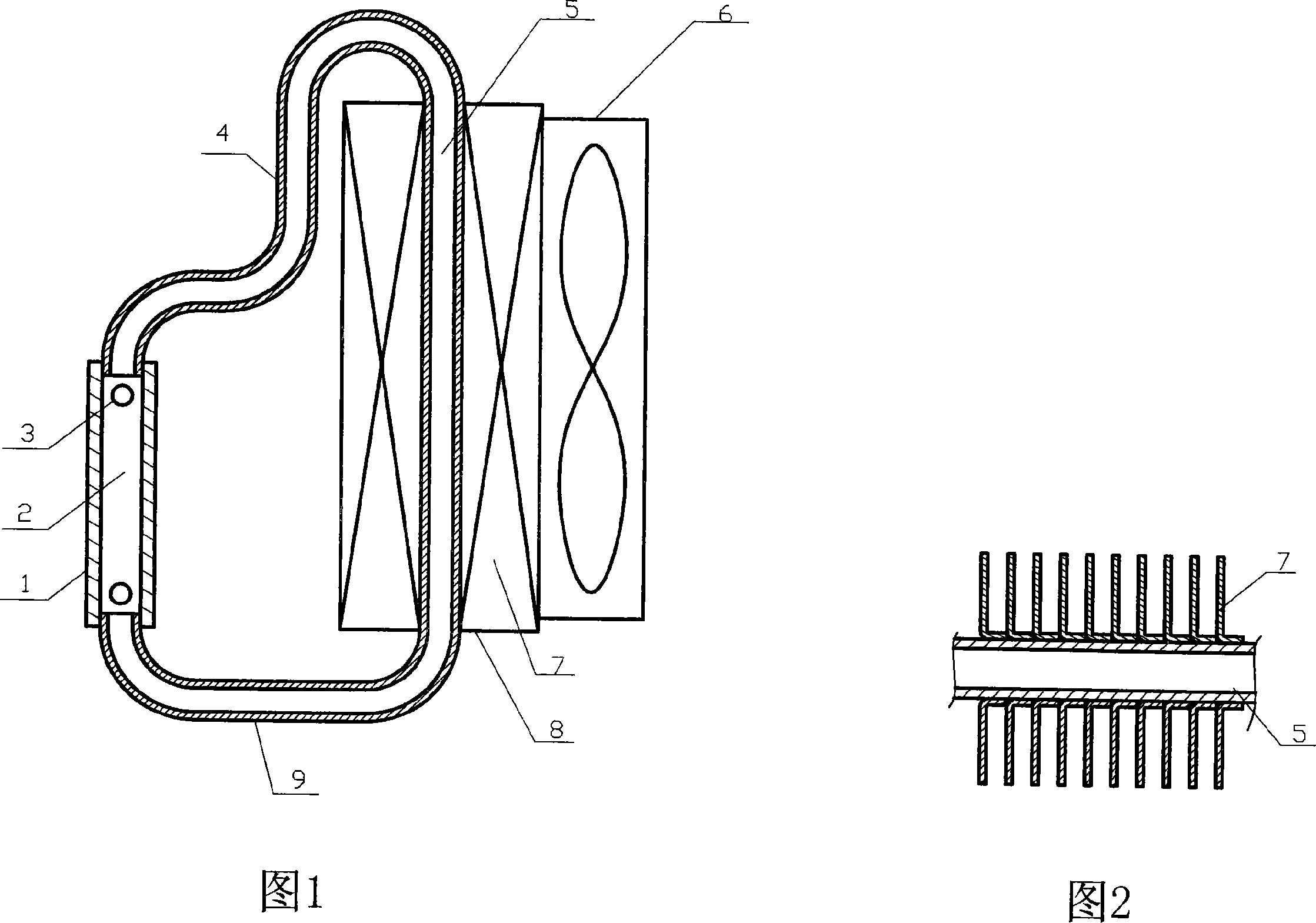
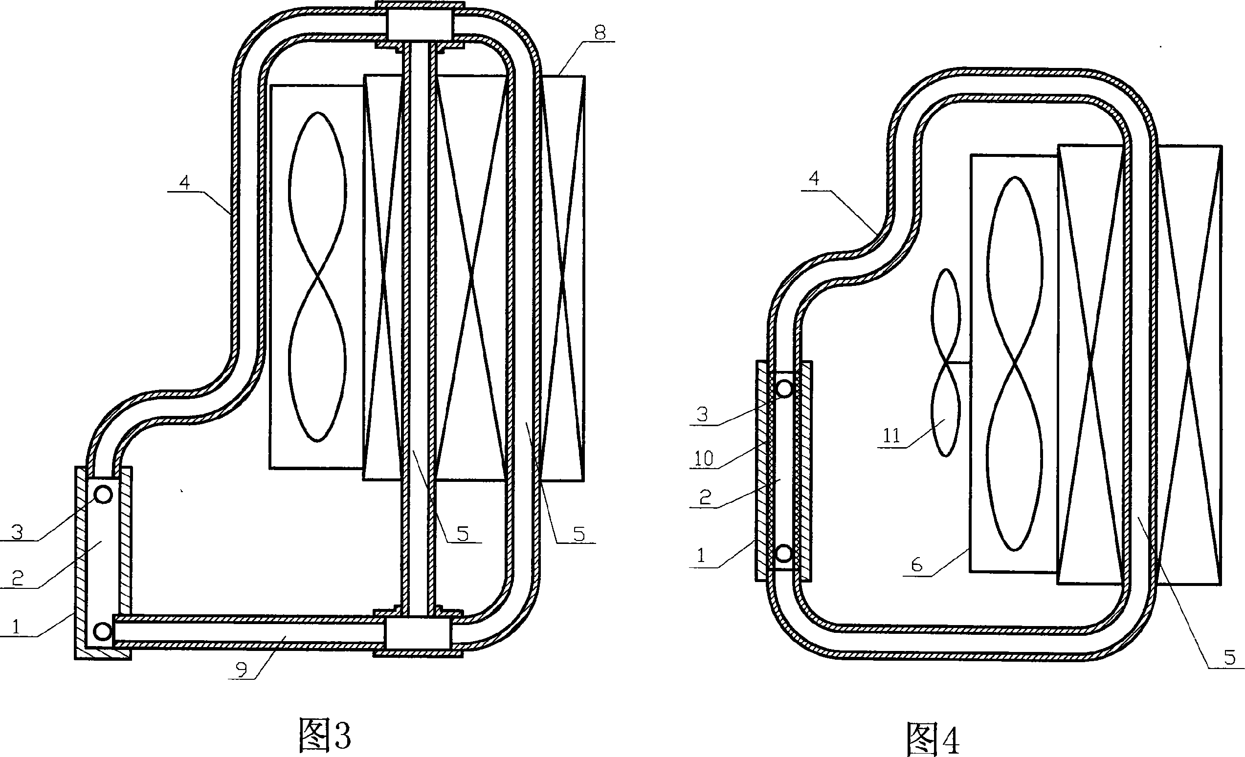
[0020] The CPU in the computer is usually placed vertically, and the radiators shown in Figures 1, 3 and 4 are placed vertically in accordance with the heat dissipation surface of the heating device. The heat-absorbing blocks (1) are all located at the lower end of the radiator, which is beneficial to the area of ​​the evaporation channel (2) in the heat-absorbing block (1) being wetted by the liquid working medium, which is conducive to evaporation and heat transfer , which is also conducive to reducing the inner area of ​​the liquid working medium submerged in the heat exchange tube (5), which is beneficial to condensation and heat transfer. In the radiator shown in Figure 3, the air heat exchanger (8) is higher than the heat-absorbing block (1), so when the evaporating channel (2) is completely submerged by the liquid working fluid, no air remains in the heat exchange tube (5). Liquid working medium, this design is good for evaporation heat transfer and condensation heat tr...


PUM


Abstract

This invention relates to a heat pipe radiator of a circulation structure applying the thermal siphon theory, which can apply high efficient and cheap expand tube technology to solve the problem of contact heat resistance by introducing an intensified cross-vetilation heat-transmission structure to optimize the design of fins, which not only reduces cost for raw materials and manufacture but also increases heat radiation volume.

Description

Technical field [0001] The invention relates to the technical field of heat dissipation of electronic devices, in particular to the heat dissipation of semiconductor integrated circuit devices and semiconductor power devices. Background technique [0002] As the number of transistors in semiconductor integrated circuits increases and the power of semiconductor power devices increases, the heat generated by the devices also increases. At present, the problem of heat generation and heat dissipation of the computer chip CPU has become an obstacle in the development of computers. The radiator with a simple fin and fan structure can no longer meet the requirements. At present, heat pipe radiators are generally used. [0003] The basic structure of the heat pipe currently used in the CPU radiator is: both ends are sealed, and there is a copper tube with a capillary structure inside. Since the CPUs in desktop computers are all placed vertically, the heat pipes in the heat pipe rad...

Claims


Application Information

Patent Timeline
Patent Type & Authority Applications(China)
IPC IPC(8): H01L23/34G06F1/20H05K7/20
Inventor 秦彪
Owner 秦彪
Why Eureka
Try Eureka