Deep-etched SiO2 ridge waveguide and its preparing process

A technology of silica and ridge waveguide, which is applied in light guides, optics, instruments, etc., can solve the problems of complex structure or process of mode matchers, increased fiber coupling loss, and reduced bending radius, so as to improve optical integration, Effects of improving film quality and reducing bending radius

Inactive Publication Date: 2006-03-08
ZHEJIANG UNIV
View PDF0 Cites 12 Cited by
  • Summary
  • Abstract
  • Description
  • Claims
  • Application Information

AI Technical Summary

Problems solved by technology

However, for this kind of waveguide with high refractive index difference, on the one hand, it is necessary to re-determine and optimize the film deposition process conditions to ensure the quality of the film; on the other hand, the size of the waveguide is reduced to 3-4 microns, which greatly increases the coupling loss with the optical fiber. Although some people use various mode matchers to reduce the coupling loss with the optical fiber, the structure or process of the mode matcher is relatively complicated, and the bending radius is not reduced by an order of magnitude.
Therefore the high refractive index difference SiO 2 Buried waveguides are not ideal either

Method used


Image

  • Deep-etched SiO2 ridge waveguide and its preparing process
  • Deep-etched SiO2 ridge waveguide and its preparing process
  • Deep-etched SiO2 ridge waveguide and its preparing process

Examples


Embodiment Construction

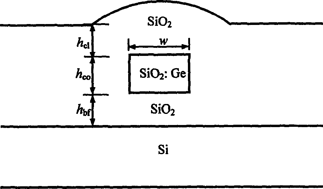
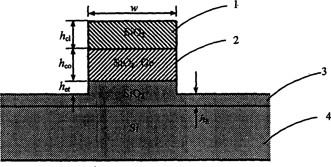
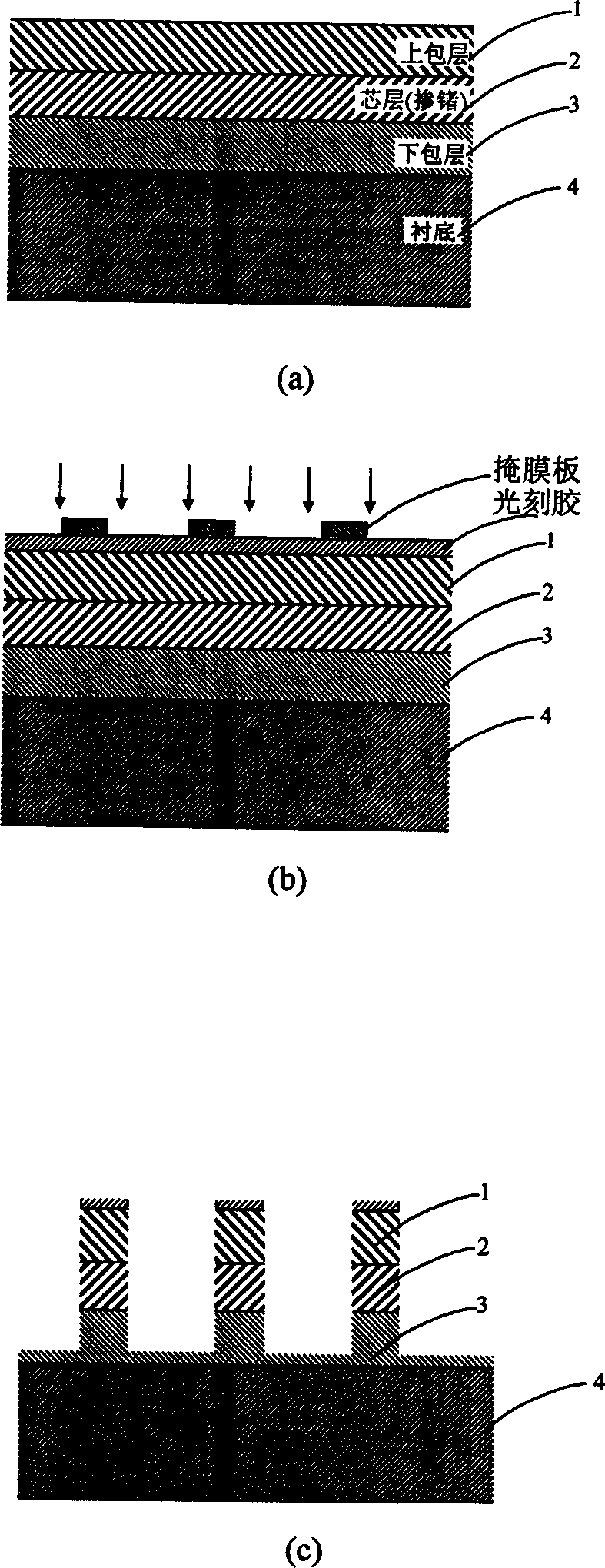
[0022] Such as figure 2 As shown, a deep-etched silica ridge waveguide includes an upper cladding layer 1, a core layer 2, a lower cladding layer 3, and a substrate 4 in sequence, and the lower cladding layer 3, core layer 2, and upper cladding layer 3 are sequentially deposited on On the substrate 4; it is characterized in that the etching depth is greater than the total thickness of the upper cladding layer 1 and the core layer 2, that is, the upper cladding layer 1, the core layer 2 and part or all of the lower cladding layer 3 are etched through.

[0023] The refractive index of the core layer 2 is slightly larger than the refractive index difference between the upper cladding layer 1 and the lower cladding layer 3, so the light field can be effectively confined in the vertical direction. Since the etching depth is sufficiently deep, the large refractive index difference between the core layer and the air in the horizontal direction can form a strong confinement, so that ...


PUM


Abstract

This invention discloses deep etched silicon dioxide rib waveguides and preparation thereof, which contains in turn depositing lower cladding, core cladding and upper cladding on substrate by silicon dioxide film deposition technology, etching penetrating upper cladding and core cladding by deep etching technology, etching part or all lower cladding, In said invention, the light field limitation is increased with reduced curve semidiameter and raised light integrity.

Description

technical field [0001] The invention relates to the field of planar optical waveguide integration, in particular to a deeply etched silicon dioxide ridge waveguide and a preparation process thereof. Background technique [0002] Silicon-based silica (SiO 2 ) waveguide is the most widely used of all kinds of planar optical waveguides. It has the following outstanding advantages, such as stable properties, mature technology, the same light transmission window as optical fibers, good mode spot matching, high coupling efficiency, and small propagation loss. Wait. At present, the most widely used is the buried rectangular waveguide, with a structure such as figure 1 As shown, the refractive index of the cladding layer and the refractive index of the core layer are n 1 , n 2 (n 2 >n 1 ), when the light wave is transmitted in the buried rectangular waveguide, the energy is mainly concentrated in the rectangular core region. However, the relative refractive index differenc...

Claims


Application Information

Patent Timeline
Patent Type & Authority Applications(China)
IPC IPC(8): G02B6/036G02B6/136
Inventor 戴道锌何赛灵
Owner ZHEJIANG UNIV
Why Eureka
Try Eureka