Gap sealing arrangement

a gas turbine engine and sealing arrangement technology, applied in the direction of engine sealing, climate sustainability, sustainable transportation, etc., can solve the problems of fluid leakage, the most prevalent leakage, and the negative impact of fuel burn of gas turbine engines, so as to achieve the effect of reducing the overall weight of the seal

Inactive Publication Date: 2008-02-28
TECH UNITED
View PDF19 Cites 18 Cited by
  • Summary
  • Abstract
  • Description
  • Claims
  • Application Information

AI Technical Summary

Benefits of technology

[0008]In accordance with the present invention, there is provided a compliant seal assembly for restricting leakage between components. Leaf strips made of a compliant material are stacked flat and sandwiched between a back plate and a side plate. The leaf strips are secured to the plates along an edge of the strips in contact with the plates. Since the strips are secured to the back and side plates only where they contact the plates, an overall weight reduction of the seal results.

Problems solved by technology

The fuel burn of a gas turbine engine may be negatively impacted if pressurized compressor air leaks through gaps or if the expanding gas leaks around the bladed turbine rotors.
Fluid leakage can occur at stationary component interfaces where gaps exist, but leakage is most prevalent at the interfaces between rotating and stationary components.

Method used


Image

  • Gap sealing arrangement
  • Gap sealing arrangement
  • Gap sealing arrangement

Examples


Embodiment Construction

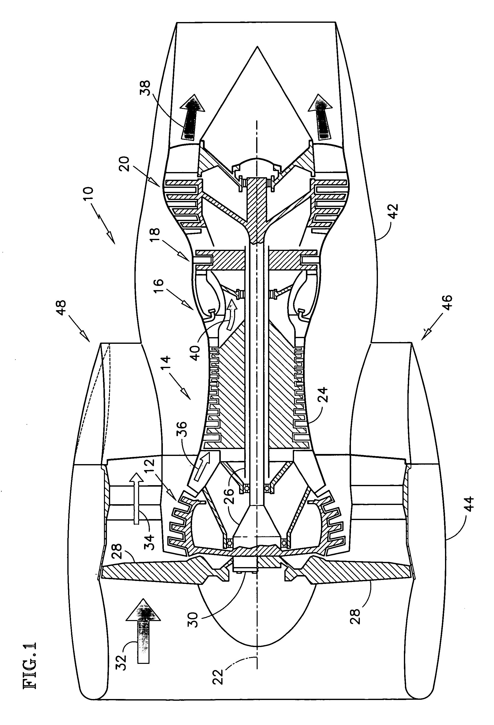
[0020]A gas turbine engine 10 of FIG. 1 includes in series from front to rear, rotating low-pressure 12 and high-pressure 14 compressors, a stationary combustor 16 and rotating high-pressure 18 and low-pressure 20 turbines. Each section is disposed about a central, longitudinal axis 22 of the engine 10 and enclosed within cylindrical casing structures 24. The turbines 18, 20 are coupled to the compressors 14, 12 via one or more centrally mounted, concentric shafts 26. A forward most fan 28 may be driven directly by a shaft 26 along with the low-pressure compressor 12 or driven independently by a gearbox 30 attached to a shaft 26.

[0021]Ambient air 32 is drawn into the engine 10 by the fan 28 and immediately directed into two fluid streams: a bypass fluid 34 and a working fluid 36. The bypass fluid 34 is directed radially outboard of the casing structure 24. The working fluid 36 is pressurized in the compressors 12, 14 and directed into the combustor 16, where fuel is injected and the...


PUM


Abstract

Disclosed is a compliant seal arrangement 50 for restricting leakage through a gap between a first 54 and second 56 component. A seal assembly 58 is formed by stacking leaf strips 70 flat and sandwiching the stacked leaf strips 70 between a back plate 76 and a side plate 78. The leaf strips 70 are secured to the plates at a joint 84 along an edge 86 of the strips 70 that are in contact with the plates 76, 78. The seal assembly 58 is installed across the gap 52 to form the seal arrangement 50. The strips 70 extend from the first component 54, bridge the gap 52 and contact the second component 56, thereby restricting the leakage of fluid through the gap. Because the strips 70 are compliant, relative motion between the components 54, 56 deflects the strips 70, not causing permanent deformation.

Description

[0001]This invention was made with Government support under F33657-89-2014 awarded by the United States Air Force. The Government has certain rights in this invention.BACKGROUND OF THE INVENTION[0002](1) Field of the Invention[0003]The invention relates to gas turbine engine components in general, and more specifically to a sealing arrangement for restricting leakage of a pressurized fluid through a gap formed between such components.[0004](2) Description of the Related Art[0005]Gas turbine engines operate according to a continuous-flow, Brayton cycle. Ambient air is pressurized in a forward compressor section, fuel is added to the air and the mixture is burned in a central combustor section, and the combustion gases are expanded through a rearward turbine section before being expelled from a rearmost nozzle. Bladed rotors in the turbine section convert thermodynamic energy from the expanding gases into mechanical energy to rotate centrally mounted, longitudinal shafts. The rotating...

Claims


Application Information

Patent Timeline
Patent Type & Authority Applications(United States)
IPC IPC(8): F16J15/44
CPCF01D11/003F01D11/08F16J15/3292F05D2230/237F05D2240/57F05D2230/232Y02T50/671Y02T50/60F05D2240/59
Inventor BAIRD, DONALD J.CINI, COLIN L.
Owner TECH UNITED
Why Eureka
Try Eureka