Floor configuration having enhanced isolation degree between two antennas

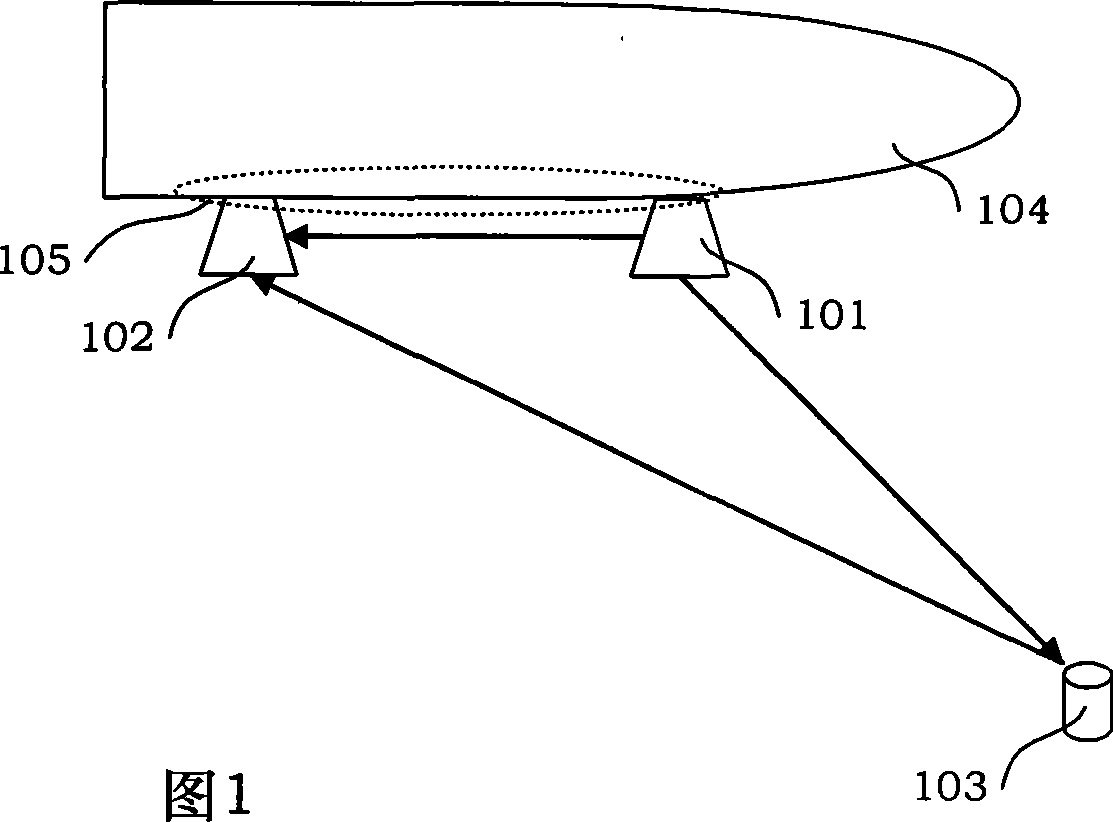
An isolation and antenna-to-antenna technology, applied in antenna coupling, suitable for antennas on movable objects, etc., can solve the problem of high radiation intensity of transmitting microstrip antenna 101, low detection accuracy of ground objects 103, misjudgment of relative height, etc. problems, to achieve the effect of improving electromagnetic interference, simple structure, and little impact on aerodynamics

Active Publication Date: 2009-05-06
BEIHANG UNIV
View PDF0 Cites 5 Cited by
  • Summary
  • Abstract
  • Description
  • Claims
  • Application Information

AI Technical Summary

Problems solved by technology

The transmitting microstrip antenna 101 and the receiving microstrip antenna 102 are generally installed in parallel at the belly 105 of the aircraft. Since there is no obstruction between the two antennas, and the two antennas are relatively close (400-600mm) to cause mutual interference between the two antennas, The detection accuracy of the ground object 103 is not high, and the target is not clear
[0004] Above-mentioned two airborne antenna EMC problems, its essential cause all is because the radiation intensity of transmitting microstrip antenna 101 is too large in the lateral direction or the receiving gain of receiving microstrip antenna 102 is too high in the lateral direction, thereby causing the ground object 103 and Misjudgment of relative altitude of aircraft 104

Method used


Image

  • Floor configuration having enhanced isolation degree between two antennas
  • Floor configuration having enhanced isolation degree between two antennas
  • Floor configuration having enhanced isolation degree between two antennas

Examples


Embodiment

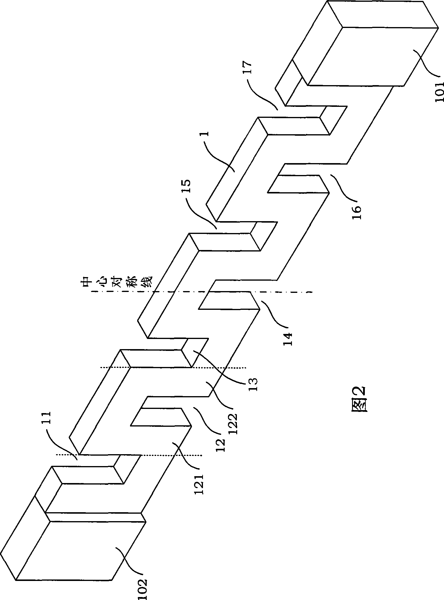
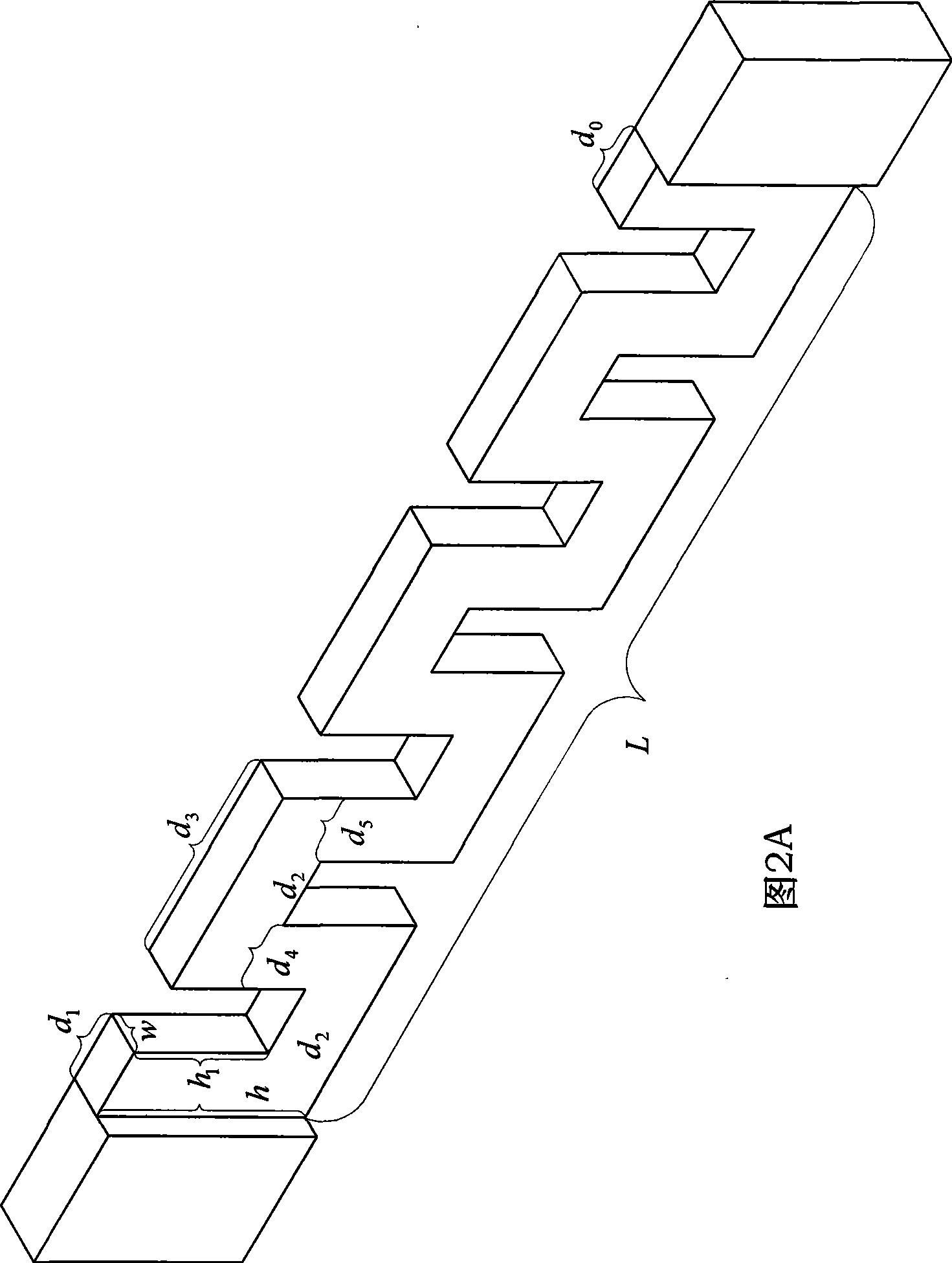
[0021] The specific structure is shown in Fig. 2 and Fig. 2A.

[0022] Floor (metal skin) L=150mm, h=28mm (the operating wavelength λ of the transmitting microstrip antenna 101 is about 70mm), w=1mm.

[0023] The distance d between the crenel 11 on A and the receiving microstrip antenna 102 1 =10mm, the distance d between the crenel 17 and the transmitting microstrip antenna 101 on D 0 = 10 mm.

[0024] On the upper and lower edges of the metal skin of length L, a plurality of rectangular openings (the size of the rectangular opening is h 1 =18mm, d 2 =10mm), that is, the upper part of the metal skin is provided with A upper crenel 11, B upper crenel 13, C upper crenel 15, D upper crenel 17; the lower part of the metal skin is opened with A lower crenel 12, B lower crenel 14, C 16 lower crenels. The distance d between the crenel 11 on A and the crenel 13 on B 3 = 30mm, then d 4 、d 5 10mm respectively.

[0025] In order to verify the above-mentioned floor structure, us...


PUM


Abstract

The invention discloses a floor structure which can improve the isolation between antennas. A plurality of upper crenels and lower crenels with identical structures are arranged on the floor, the widths of the upper crenels and the lower crenels are equal, and a lower crenel is arranged between two adjacent upper crenels; conversely an upper crenel is arranged between two adjacent lower crenels; and a transmitting microstrip antenna and a receiving microstrip antenna are respectively connected with both ends of the floor. The floor structure improves the electromagnetic interference between airborne antennas. The method prolongs the transmission path of the electromagnetic wave between interference antennas, increases the attenuation loss of the electromagnetic wave, and can basically improve the isolation between the antennas in the acceptable antenna radiation characteristic distortion range.

Description

technical field [0001] The invention relates to a floor configuration for parallel installation between two microstrip antennas on the belly of an aircraft and having improved isolation between the two antennas. Background technique [0002] With the development of electronics and communication technology, the application of radio equipment with various functions is becoming more and more extensive. Especially on aircraft, in order to meet the needs of communication and navigation, the number of antennas on the airborne platform has doubled, and multiple antennas work simultaneously in a small area, causing serious electromagnetic interference. The main transmission path of electromagnetic interference between radio systems is the coupling between antennas. In order to realize the normal work between the antennas and avoid mutual interference, it is required to reduce the harmful coupling between the antennas. Therefore, improving the antenna isolation has become a prerequ...

Claims


Application Information

Patent Timeline
Patent Type & Authority Applications(China)
IPC IPC(8): H01Q1/52H01Q1/28
Inventor 陈爱新侯燕春汪玉梅苏东林王龙峰王义
Owner BEIHANG UNIV
Why Eureka
Try Eureka