Railcar coupler system and method

a coupler and railcar technology, applied in the field of railcars, can solve the problems of train delays, labor-intensive failure of couplers, etc., and achieve the effect of reducing or eliminating at least some of the disadvantages and problems

Active Publication Date: 2010-07-20
MCCONWAY & TORLEY LLC
View PDF30 Cites 25 Cited by
  • Summary
  • Abstract
  • Description
  • Claims
  • Application Information

AI Technical Summary

Benefits of technology

[0004]The present invention provides a railcar coupler system and method that substantially eliminates or reduces at least some of the disadvantages and problems associated with previous systems and methods.
[0008]Technical advantages of particular embodiments include a coupler having a guard arm portion that is smaller and narrower than conventional guard arm portions. In addition, guard arm portions in some embodiments may not include internal cavities formed by cores. Thus, the process of inspection to ensure that couplers and associated guard arm portions meet desired standards and criteria is eased. In addition, with the lack of cavities and associated sidewalls and the simplified guard arm portion configuration, the finishing process for the coupler and guard arm portion in particular is simplified. The smaller guard arm portion size may also reduce the total weight of the coupler. In addition, some embodiments include the process of manufacturing a coupler by attaching a guard arm portion to a coupler body after the coupler body has been cast which reduces complexities in the coupler manufacturing process. Moreover, some embodiments may include a chain lug hole on the guard arm portion and formed after casting through a drilling, punching or other process thereby reducing additional labor and expense in the manufacturing process.

Problems solved by technology

The repair of a failed coupler can be labor intensive, can sometimes take place in very inclement weather and can cause train delays.

Method used


Image

  • Railcar coupler system and method
  • Railcar coupler system and method
  • Railcar coupler system and method

Examples


Embodiment Construction

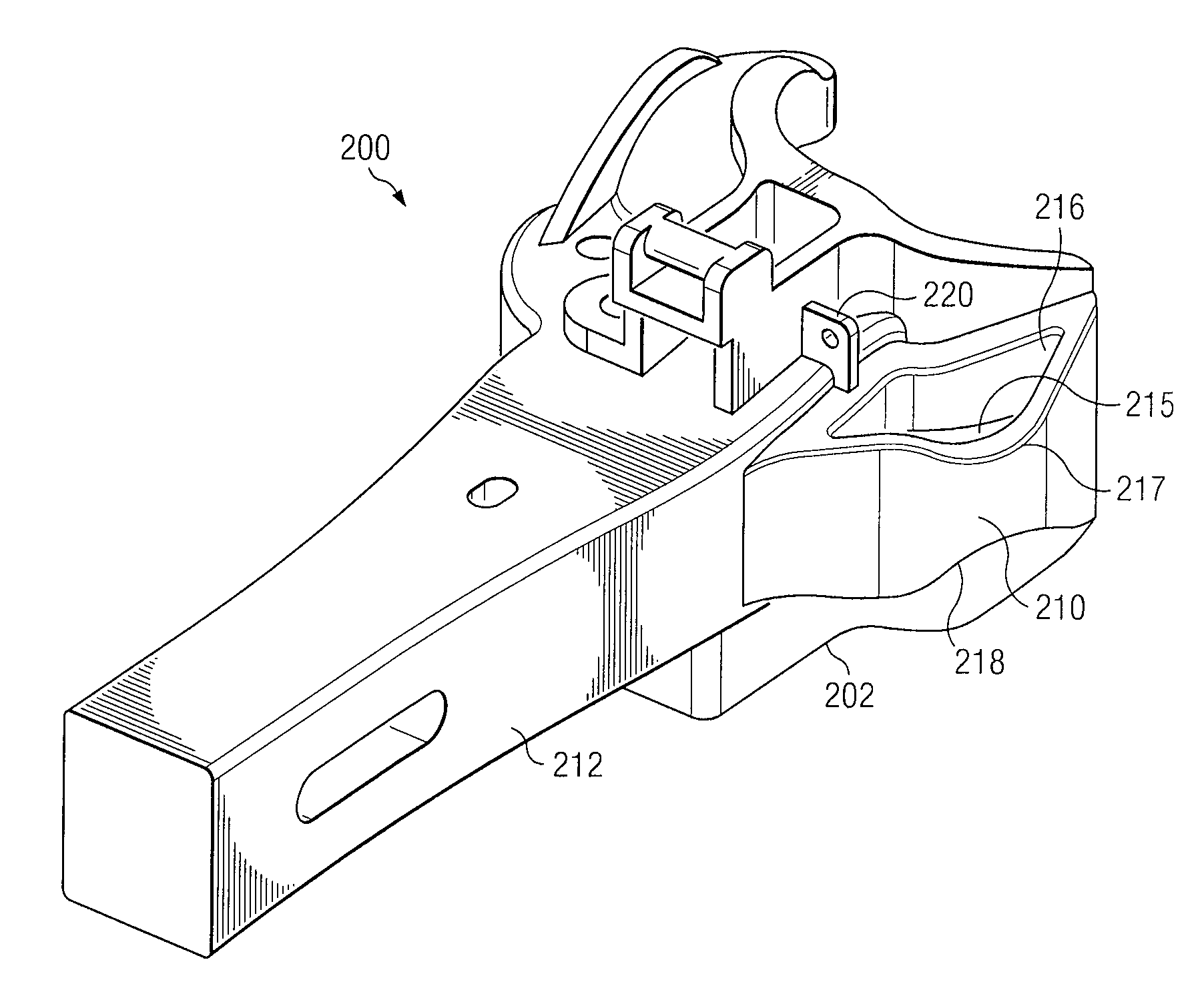
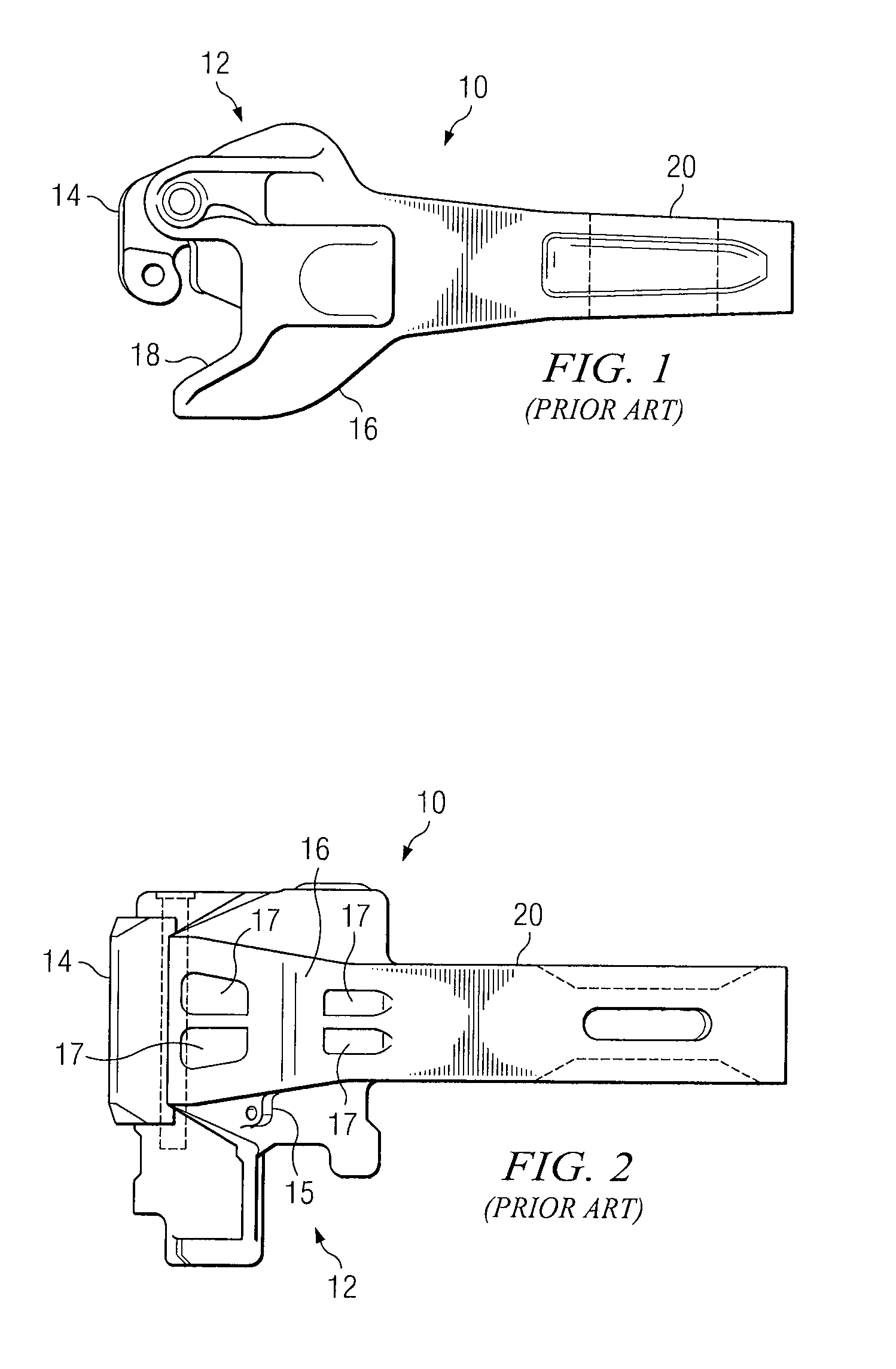
[0018]FIGS. 1 and 2 illustrate a coupler 10 for freight railway cars in accordance with standard specifications as set forth by the Mechanical Committee of Standard Coupler Manufacturers. Coupler 10 is mounted within a yoke secured at each end of a railway car center sill, such that it may extend outwardly under an end of a railway car to engage a similar coupler extending outwardly under an end of an adjacent railway car. Coupler 10 includes a generally V-shaped coupler head 12 at a forward end extending from a shank 20. Shank 20 is adapted to be fitted within and attached to a yoke secured at each end of a center sill extending full length under the railway car at a longitudinal axis.

[0019]Coupler head 12 has a vertical-knuckle 14 rotatably pinned at an outer end of coupler head 12 forming a first leg of coupler head 12, while a second leg of coupler head 12 comprises a fixed and rigid guard arm portion 16 with cavities 17. Coupler 10 also includes a first angled gathering surface...


PUM

PropertyMeasurementUnit
heightaaaaaaaaaa
lengthaaaaaaaaaa
nose heightaaaaaaaaaa

Abstract

A railcar coupler includes a coupler head portion extending from a shank portion. The coupler head portion is configured to couple to a first coupler knuckle for coupling the railcar coupler to a second railcar coupler of an adjacent railcar. The coupler head portion comprises a nose portion and a gathering face extending from the nose portion for engaging a second coupler knuckle coupled to the second railcar coupler. The coupler head portion comprises a guard arm portion extending from the nose portion towards the shank portion. The guard arm portion comprises a minimum height less than a height of the shank portion where the guard arm portion meets the shank portion.

Description

TECHNICAL FIELD OF THE INVENTION[0001]This invention relates in general to railcars and, more particularly, to a railcar coupler system and method.BACKGROUND OF THE INVENTION[0002]Railcar couplers are disposed at each end of a railway car to enable joining one end of such railway car to an adjacently disposed end of another railway car. The engageable portions of each of these couplers is known in the railway art as a knuckle. For example, railway freight car coupler knuckles are taught in U.S. Pat. Nos. 4,024,958; 4,206,849; 4,605,133; and 5,582,307.[0003]In many cases when a railcar coupler fails, a replacement coupler must be carried from the locomotive at least some of the length of the train, which may be up to 25, 50 or even 100 railroad cars in length. The repair of a failed coupler can be labor intensive, can sometimes take place in very inclement weather and can cause train delays.SUMMARY OF THE INVENTION[0004]The present invention provides a railcar coupler system and meth...

Claims


Application Information

Patent Timeline
Patent Type & Authority Patents(United States)
IPC IPC(8): B61G3/00
CPCB61G3/04B22D19/12B61G3/00
Inventor MAUTINO, P. SCOTTGAGLIARDINO, JOSEPH L.SAELER, KEVIN S.
Owner MCCONWAY & TORLEY LLC
Why Eureka
Try Eureka