Hydrogen occlusive alloy, hydrogen storage film and hydrogen storage tank

a hydrogen storage film and alloy technology, applied in cell components, packaging goods types, transportation and packaging, etc., can solve the problems of hardly functioning as hydrogen storage materials and very little hydrogen release, and achieve excellent hydrogen occlusion and release properties

Active Publication Date: 2010-07-20
KK TOSHIBA +1
View PDF8 Cites 2 Cited by
  • Summary
  • Abstract
  • Description
  • Claims
  • Application Information

AI Technical Summary

Benefits of technology

[0014]The object of the present invention is to provide a hydrogen occlusion alloy having an excellent hydrogen occlusion and release property, and a hydrogen storage film and a hydrogen storage tank using the same.

Problems solved by technology

However, these magnesium-based alloys have a disadvantage that they release very little amount of hydrogen and hardly function as a hydrogen storage material, although they occlude a large amount of hydrogen in gas phase.
However, both of the electrochemical hydrogen storage material of U.S. Pat. No. 5,506,069 and the hydrogen occlusive alloy of JP-A 2002-302733(KOKAI) only release a little amount of hydrogen, and are not regarded as having an excellent hydrogen release property.

Method used


Image

  • Hydrogen occlusive alloy, hydrogen storage film and hydrogen storage tank
  • Hydrogen occlusive alloy, hydrogen storage film and hydrogen storage tank
  • Hydrogen occlusive alloy, hydrogen storage film and hydrogen storage tank

Examples


first embodiment

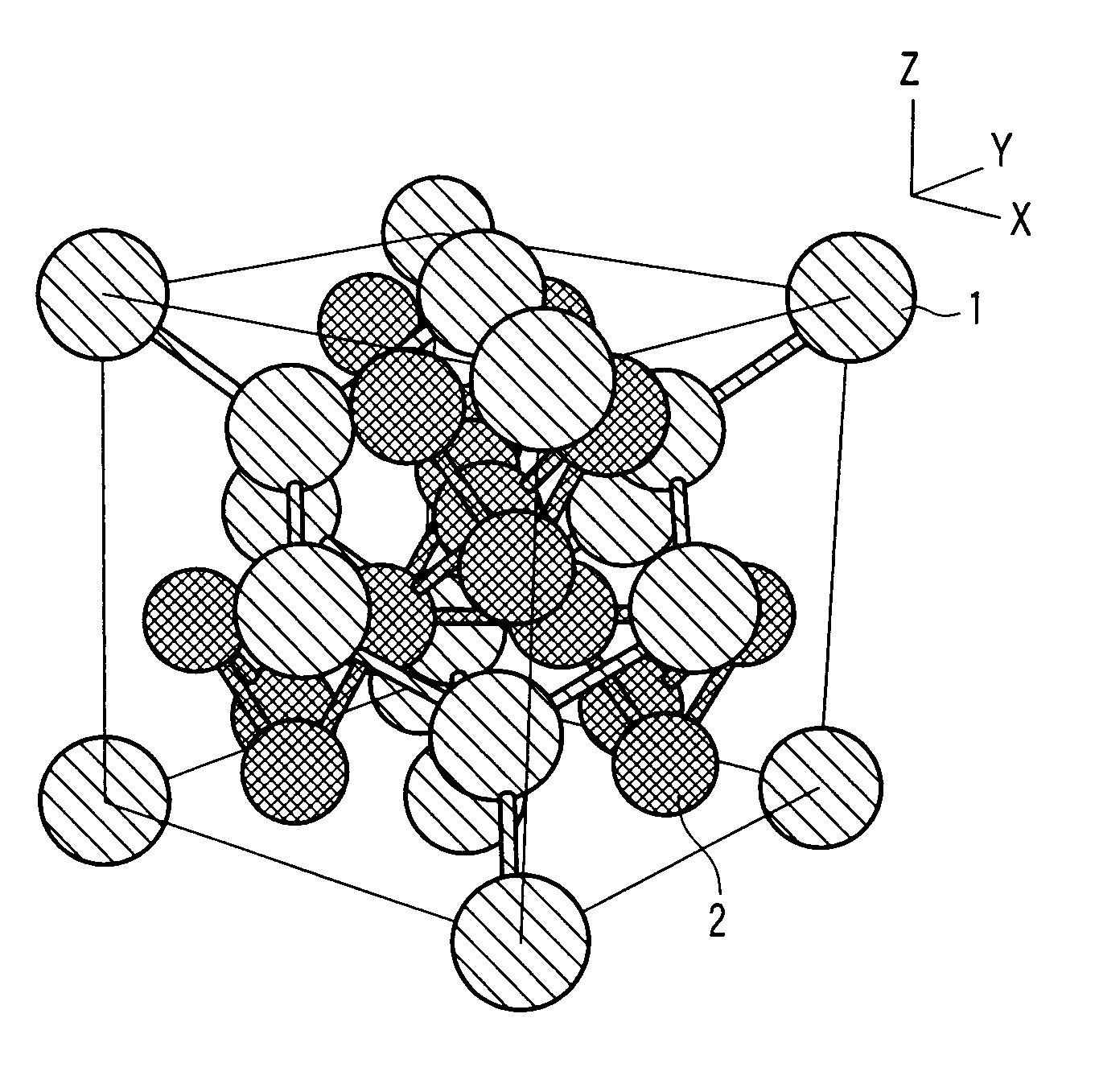
[0025]A hydrogen occlusive alloy according to a first embodiment has a cubic structure and a composition represented by the following general formula (1).

(Mg1-XLX)(Ni1-Y-ZMYLiZ)m  (1)

[0026]In the formula (1), element L is at least one element selected from the group consisting of Na, Cs, Ca, Sr, Ba, Sc, Ti, Zr, Hf, V, Nb, Ta, Y, La, Ce, Pr, Nd, Pm, Sm, Eu, Gd, Tb, Dy, Ho, Er, Tm, Yb, and Lu. When reduction in the cost of the alloy is considered, at least one element selected from the group consisting of Ca, Ti, Zr, V, Nb, Ta and Y is preferably used as the element L, more preferably any of Ca, Ti, Zr, and V. When the hydrogen release property is considered, it is preferable to use at least one element as the element L selected from the group consisting of Ca, Hf, Sr and rare-earth elements (Y, La, Ce, Pr, Nd, Pm, Sm, Eu, Gd, Tb, Dy, Ho, Er, Tm, Yb, Lu).

[0027]The range of the mole ratio X is 0

second embodiment

[0039]The hydrogen occlusive alloy according to the first embodiment can be formed into a film shape. The hydrogen occlusive alloy having a film shape can function as a hydrogen storage film which displays an excellent hydrogen occlusive and release property.

[0040]The hydrogen storage film may contain alloys other than the hydrogen occlusive alloy. The hydrogen occlusive alloy preferably occupies a volume of at least 70 vol % in the hydrogen storage film. When the percentage of the hydrogen occlusive alloy is less than 70 vol %, a different phase may be precipitated with a large amount, and the performance as a hydrogen occlusive material may be deteriorated.

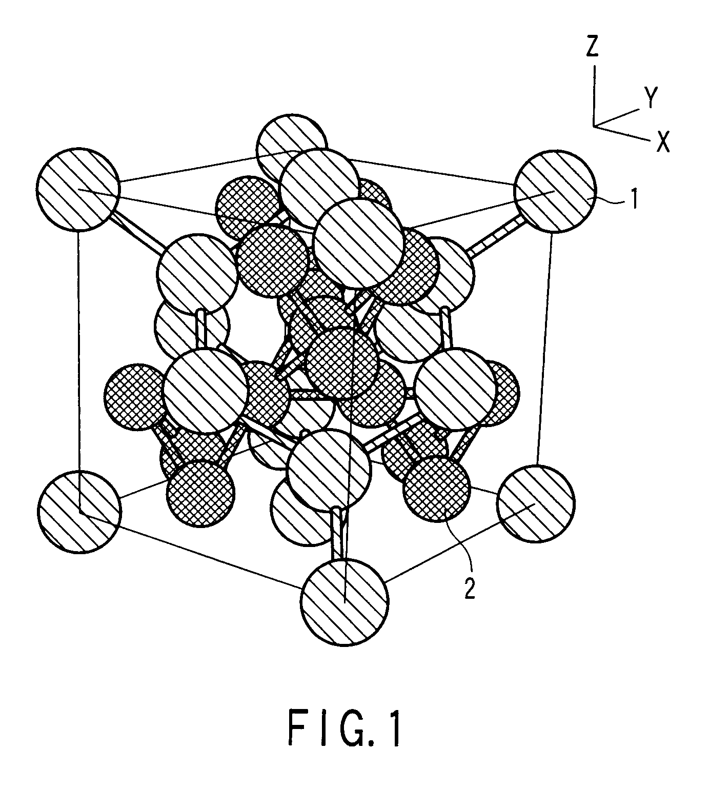
[0041]The hydrogen storage film is explained with reference to FIG. 2.

[0042]FIG. 2 is a schematic cross-sectional diagram of a hydrogen separating device using the hydrogen storage film according to the second embodiment as a hydrogen separation film.

[0043]A hydrogen separating device 20 illustrated in FIG. 2 comprises a high-pr...

third embodiment

[0047]The hydrogen occlusive alloy according to the first embodiment can be used in a powder form. The particles forming the powder are not limited to a specific shape. For example, the particles may have a spherical shape or may be flakes. Powder of the hydrogen occlusive alloy can be used as a filling material for a hydrogen storage tank which exhibits an excellent hydrogen occlusion and release property. The filling material may contain alloys other than the hydrogen occlusive alloy. The ratio of the hydrogen occlusive alloy and the other alloys may be the same as that explained in the second embodiment.

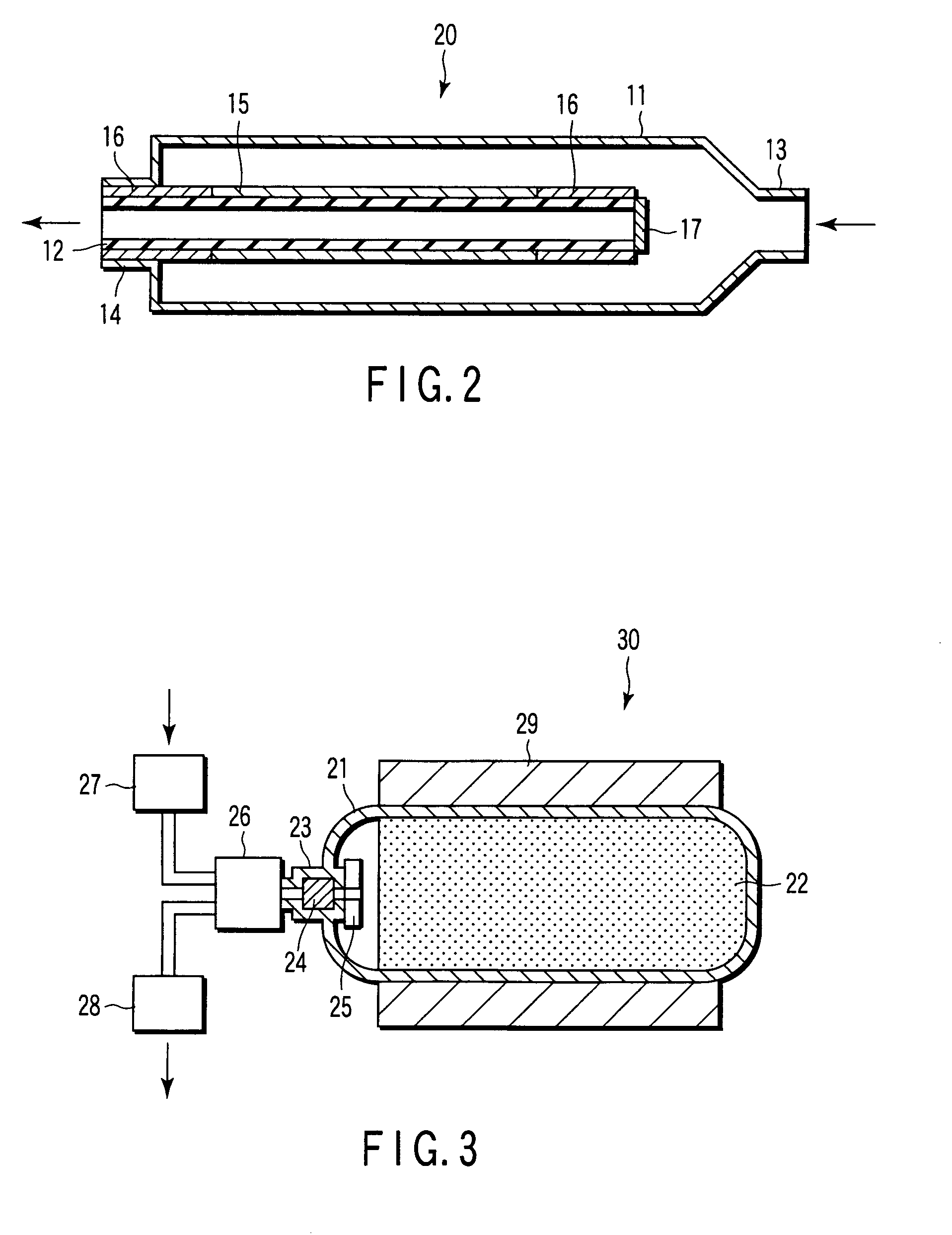
[0048]The hydrogen storage tank is described with reference to FIG. 3.

[0049]FIG. 3 is a schematic cross-sectional view of the hydrogen storage tank according to a third embodiment.

[0050]A hydrogen storage tank 30 comprises a pressure vessel (pressure-resistant vessel) 21, and a hydrogen occlusive material 22 filled into the pressure vessel 21 and serving as a filling material. Pow...


PUM

PropertyMeasurementUnit
temperatureaaaaaaaaaa
mole ratioaaaaaaaaaa

Abstract

A hydrogen occlusive alloy has a cubic structure and a composition represented by the following general formula (1):(Mg1-XLX)(Ni1-Y-ZMYLiZ)m  (1)where the element L is at least one element selected from the group consisting of Na, Cs, Ca, Sr, Ba, Sc, Ti, Zr, Hf, V, Nb, Ta, Y, La, Ce, Pr, Nd, Pm, Sm, Eu, Gd, Tb, Dy, Ho, Er, Tm, Yb, and Lu, the element M is at least one element selected from the group consisting of Cr, Mo, W, Mn, Fe, Co, Pd, Pt, Cu, Ag, Zn, Cd, B, Al, Ga, In, Si, Ge, Sn, Pb, Sb and Bi, and mole ratios X, Y, Z and m are 0<X≦0.5, 0<Y≦0.5, 0.1≦Z≦0.9, and 1.8≦m≦2.2, respectively.

Description

CROSS-REFERENCE TO RELATED APPLICATIONS[0001]This application is based upon and claims the benefit of priority from prior Japanese Patent Application No. 2006-095337, filed Mar. 30, 2006, the entire contents of which are incorporated herein by reference.BACKGROUND OF THE INVENTION[0002]1. Field of the Invention[0003]The present invention relates to a hydrogen occlusive alloy, a hydrogen storage film, and a hydrogen storage tank.[0004]2. Description of the Related Art[0005]Hydrogen occlusive alloys are alloys which store hydrogen as an energy source safely and easily. Therefore, hydrogen occlusive alloys have received much attention as a new energy conversion and storage material. The application field of hydrogen occlusive alloys as a new functional material covers a wide range, such as storage and transportation of hydrogen, storage and transportation of heat, conversion of heat-mechanical energy, separation and refinement of hydrogen, separation of hydrogen isotope, cells using hy...

Claims


Application Information

Patent Timeline
Patent Type & Authority Patents(United States)
IPC IPC(8): C22C30/00H01M4/38
CPCC01B3/0047C01B3/0057C22C19/03C22C30/00C22C23/00B22F2009/041B22F2998/00Y10S420/90Y02E60/327B22F9/04Y02E60/32
Inventor KOHNO, TATSUOKIORIMO, SHIN-ICHINAKAMORI, YUKO
Owner KK TOSHIBA
Why Eureka
Try Eureka