
Optical irradiation apparatus, image reading apparatus using the same, and image forming apparatus using the same

a technology of optical irradiation and image reading, which is applied in the direction of lighting and heating apparatus, optical elements, instruments, etc., can solve the problems of large power consumption of xenon lamps, large calorific value, and small optical irradiation intensity of leds

Active Publication Date: 2010-07-20
RICOH KK
View PDF58 Cites 43 Cited by
  • Summary
  • Abstract
  • Description
  • Claims
  • Application Information

AI Technical Summary

Benefits of technology

The patent describes a new optical irradiation apparatus that can effectively direct a light beam from a light source in a specific direction. This apparatus includes a light source and a light guide made of transparent material. The light guide has a specific design with multiple connecting planes that connect the incident and exit planes of the guide. The design of the guide ensures that the light beam is efficiently led from the source to the object being irradiated. This apparatus can be used in various applications such as lighting, photopolymerization, and curing.

Problems solved by technology

The xenon lamp consumes a lot of power and the calorific value is great.
However, compared with the xenon lamp, the optical irradiation intensity of the LED is generally small.
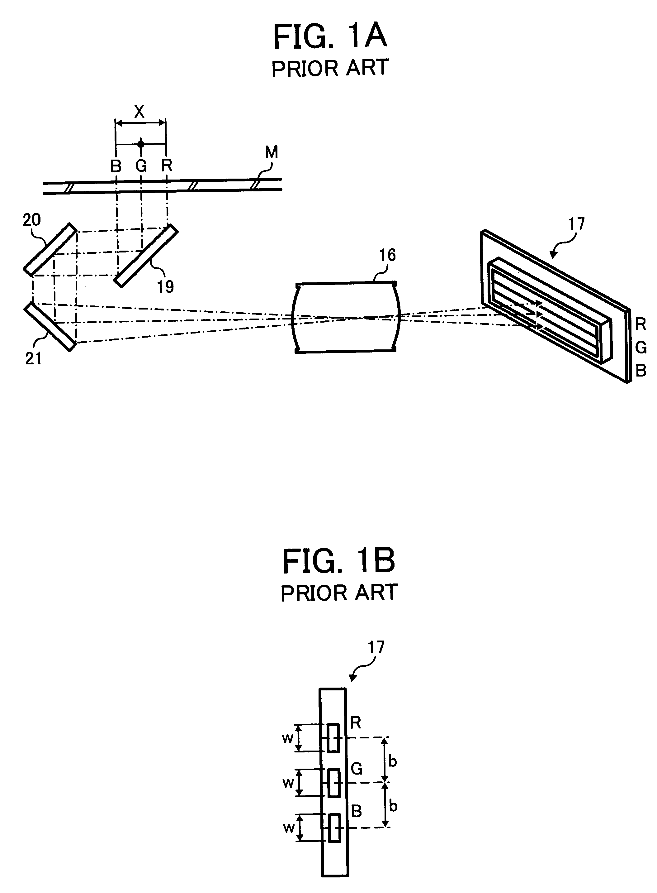
Therefore, if the LED is simply used as the light source, it is difficult to irradiate light with a sufficient intensity in the width X on the above-mentioned manuscript.
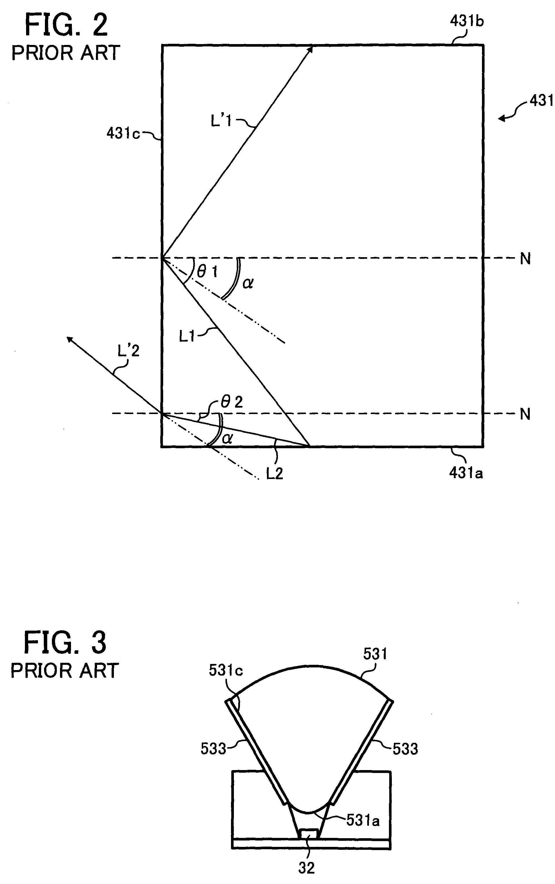
However, since it is difficult to manufacture the incidence plane 531a of the light guide 531 in a convex shape compared to a flat incidence plane, the manufacturing costs of the convex shaped incidence plane are high.
Therefore, the manufacturing costs of the conventional irradiation apparatus are high.
Thus, in the above-mentioned conventional optical irradiation apparatus, although it may prevent the incident light from exiting through the incidence plane 531a to the outside of the light guide before the light reaches the exit plane of the light guide, there is a problem that the manufacturing cost is high.

Method used


Image

  • Optical irradiation apparatus, image reading apparatus using the same, and image forming apparatus using the same
  • Optical irradiation apparatus, image reading apparatus using the same, and image forming apparatus using the same
  • Optical irradiation apparatus, image reading apparatus using the same, and image forming apparatus using the same

Examples


Embodiment Construction

[0034]In describing preferred embodiments illustrated in the drawings, specific terminology is employed for the sake of clarity. However, the disclosure of this patent specification is not intended to be limited to the specific terminology so selected and it is to be understood that each specific element includes all technical equivalents that operate in a similar manner. Referring now to the drawings, wherein like reference numerals designate identical or corresponding parts throughout the several views, FIG. 4 is an elevational view showing an outline of an internal structure of a full color copying machine 1 which is an exemplary image forming apparatus to which this invention is applied.

[0035]Although the color copying machine is mentioned as an example, the present invention is equally applicable when applied to a black and white copying machine. A printer engine 3 for forming a color image is provided in the central part of a main part 2 of copying machine 1. This printer engi...


PUM


Abstract

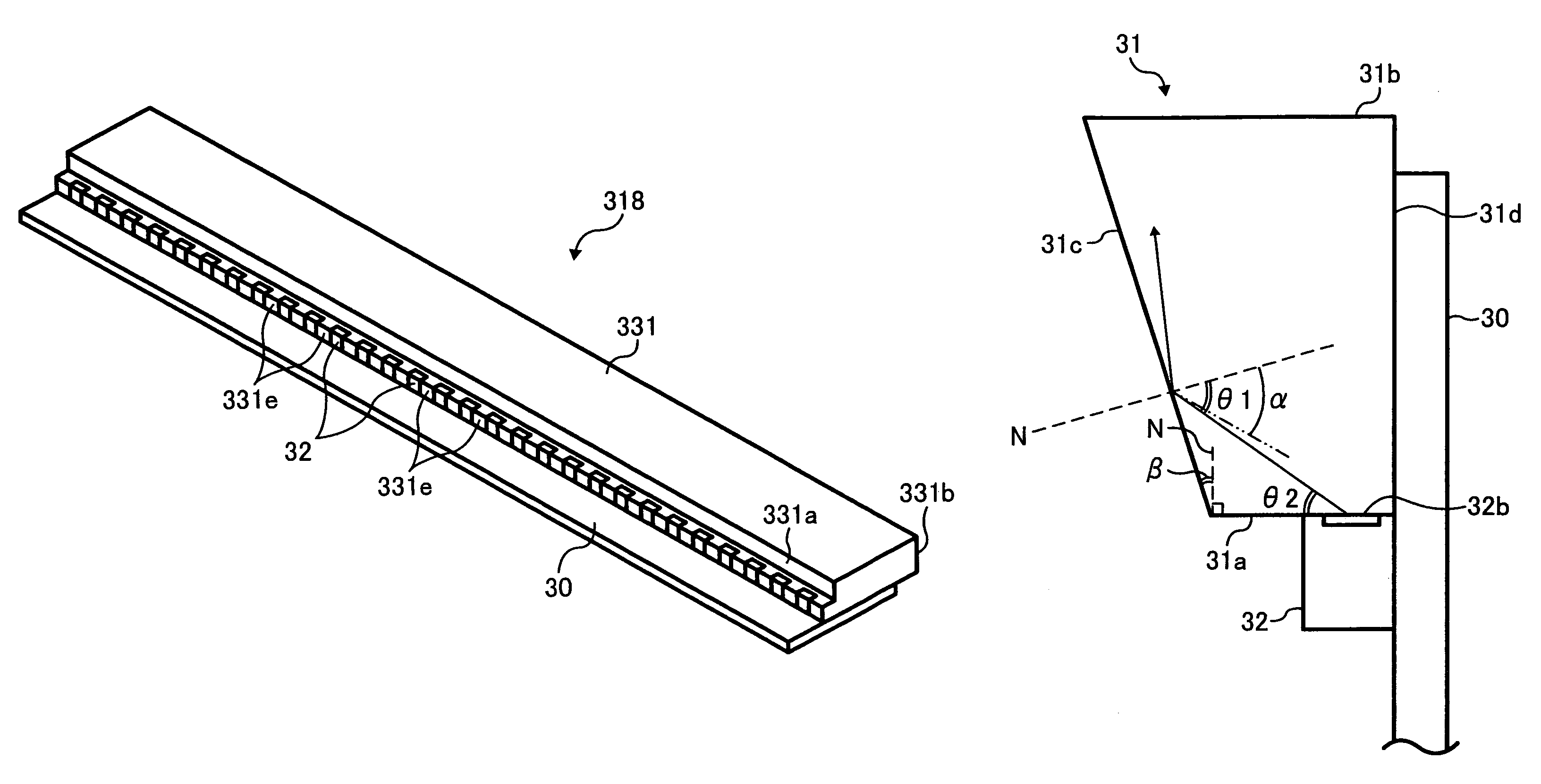
A novel optical irradiation apparatus includes a light source and a light guide. The light source is configured to radially irradiate a light beam. The light guide is configured to include a transparent material configured to lead the light beam irradiated from the light source in a specific direction and to emit the light beam. The light guide also includes an incidence plane, an exit plane, and plural connecting planes. The incidence plane is configured to receive the light beam. The exit plane is configured to emit the light beam to so as to irradiate an object. The plural connecting planes are configured to connect the incidence plane to the exit plane. A part of at least one of the plural connecting planes is inclined with respect to an axis of the light beam.

Description

BACKGROUND OF THE INVENTION[0001]1. Field of the Invention[0002]The present invention relates to an optical irradiation apparatus, an image reading apparatus, and an image forming apparatus. More particularly, the present invention relates to an apparatus having a light guide which is made of a transparent material and is capable of causing light that enters the light guide from a light source-to exit the light guide in a specific direction.[0003]2. Discussion of the Background[0004]A conventional optical irradiation apparatus is used as an optical irradiator that irradiates a manuscript in an image reading apparatus, such that a reflecting image of the manuscript is read by using, for example, a photo acceptance element such as a charge coupled devices (CCD), a complementary metal oxide semiconductor (CMOS), etc. In a case an image reading apparatus reads a color image, light reflecting from the manuscript is generally received by individual photo acceptance elements in colors of r...

Claims


Application Information

Patent Timeline
Patent Type & Authority Patents(United States)
IPC IPC(8): G02B6/00F21V7/04H04N1/04
CPCG02B6/0046G02B6/0068
Inventor SAKURAI, YASUO
Owner RICOH KK
Learn More