Parallel coefficient bit modeling

Active Publication Date: 2010-07-20
XILINX INC
View PDF5 Cites 14 Cited by
  • Summary
  • Abstract
  • Description
  • Claims
  • Application Information

AI Technical Summary

Problems solved by technology

However, a bit-serial implementation is likely to be very slow and consume hardware clock cycles on the order of 3×N2, where the code-block is N×N.
Par

Method used


Image

  • Parallel coefficient bit modeling
  • Parallel coefficient bit modeling
  • Parallel coefficient bit modeling

Examples


Embodiment Construction

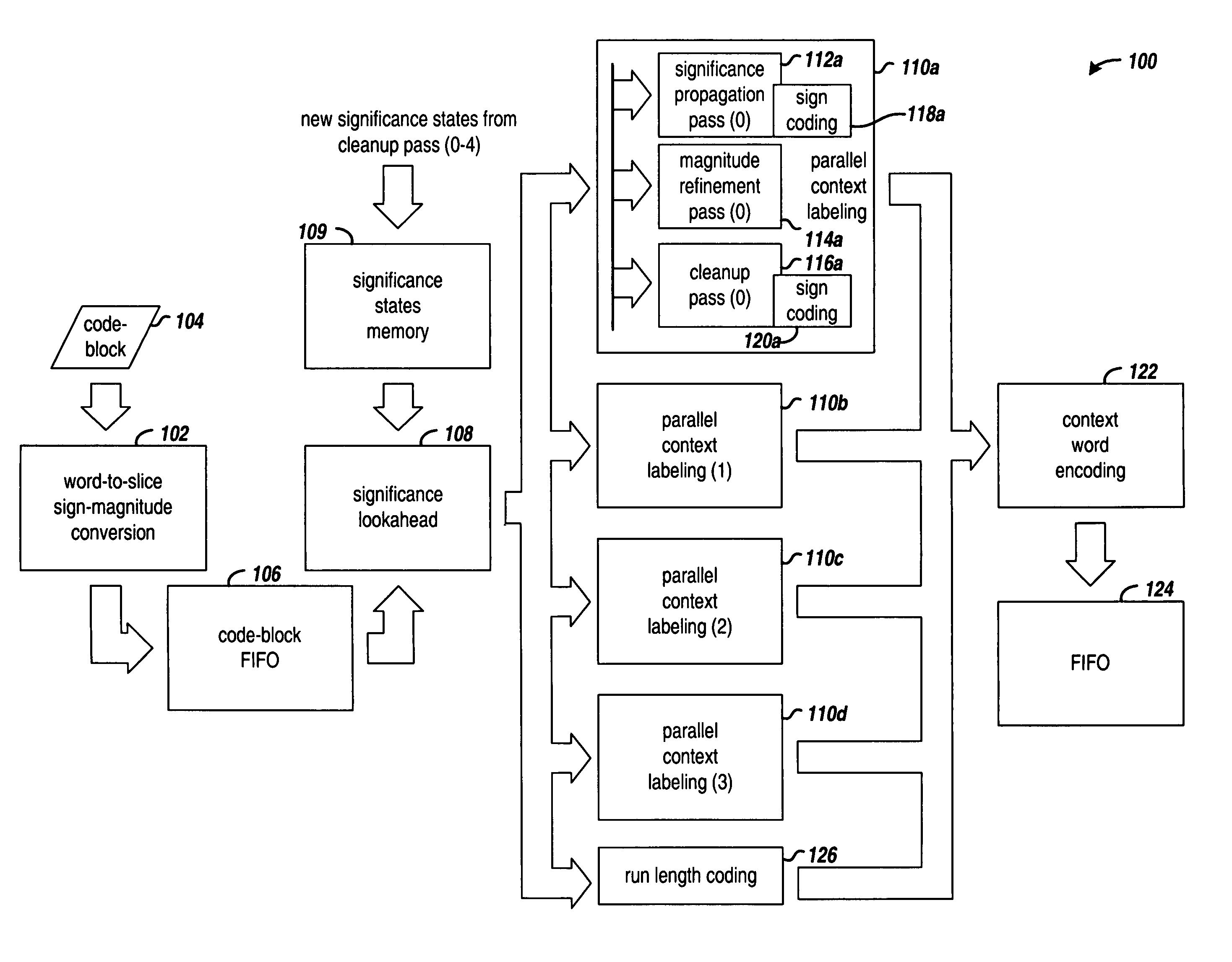
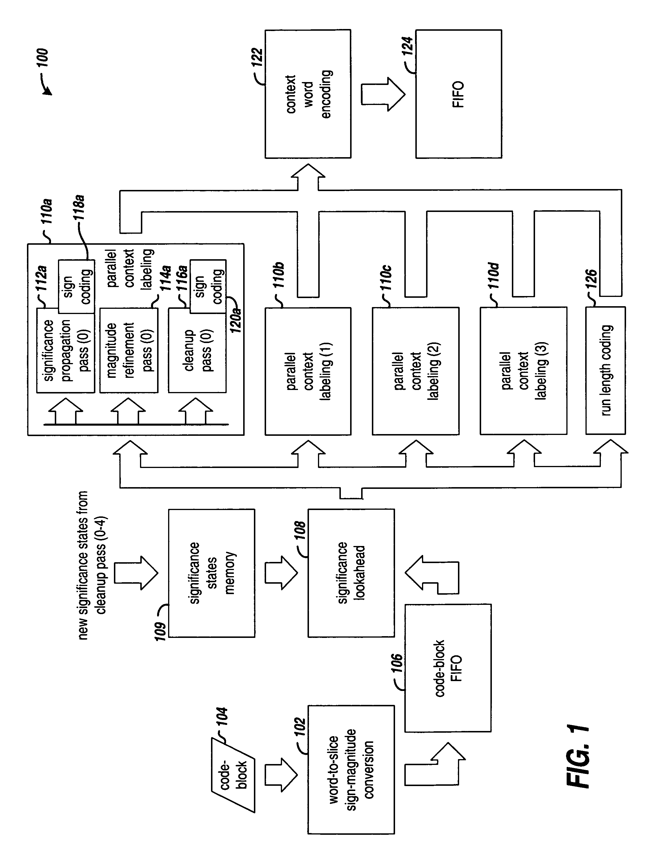
[0017]The various embodiments of the invention employ pass-level and bit-level parallelism in coefficient bit modeling. Each of the significance propagation pass, magnitude refinement pass, and cleanup pass of the context labeling are performed in parallel for pass-level parallelism. Each bitplane is processed by stripe, and the bits within a column of the stripe are processed in parallel to provide the bit-level parallelism. The significance lookahead block permits the bit and pass level parallel operation. The embodiments of the invention provide a low complexity hardware architecture that requires only N×N / 4, cycles, which is 1 / 12th the number of cycles consumed with conventional architectures. Vertically stripe-causal contexts are used in the various embodiments.

[0018]FIG. 1 is a block diagram that illustrates a circuit arrangement 100 for context bit modeling in accordance with one or more embodiments of the invention. The example embodiments are based on the vertical stripe-ca...


PUM


Abstract

A coefficient labeling circuit arrangement for bitplane coding passes in embedded block coding. In one embodiment, a significance lookahead circuit generates lookahead significance states of coefficients in past, current, and future magnitude stripe slices of a code-block containing a plurality of coefficients. A plurality of context labeling circuits are coupled in parallel to the significance lookahead circuit. Each context labeling circuit is configured with a respective significance propagation pass circuit, a respective magnitude refinement pass circuit, and a respective cleanup pass circuit. Context labels are generated in parallel for all bits of the current magnitude stripe slice.

Description

FIELD OF THE INVENTION [0001]The present invention generally relates to data compression and encoding.BACKGROUND [0002]The Joint Photographic Experts Group (JPEG) published a standard for compressing image data which became commonly known as the “JPEG standard.” The JPEG standard is based on a discrete cosine transform (DCT) compression algorithm that uses Huffman encoding. The compression is limited to 8 bits / pixel. In an effort to provide better compression quality for a broader range of applications, the JPEG developed the “JPEG 2000 standard” (International Telecommunications Union (ITU) Recommendation T.800, August 2002). The JPEG 2000 standard is based on discrete wavelet transform (DWT) and adaptive binary arithmetic coding compression.[0003]The JPEG 2000 standard generally sets forth the following approach. Input image data is partitioned into rectangular, non-overlapping tiles of equal size. The sample values in each tile are level shifted and the color data is decorrelated...

Claims


Application Information

Patent Timeline
IPC IPC(8): G06K9/36
CPCH04N19/647H04N19/436H04N19/423
Inventor RISSA, TERO
Owner XILINX INC
Why Eureka
Try Eureka