Hose clamp

a technology of hose clamps and clamping bands, which is applied in the direction of hose connections, snap fasteners, buckles, etc., can solve the problems of not only being possible, and achieve the effects of preventing the tilting reducing the internal diameter of the clamping band, and facilitating the spread of the hose clamp

Active Publication Date: 2010-07-27
NORMA GERMANY GMBH
View PDF14 Cites 18 Cited by
  • Summary
  • Abstract
  • Description
  • Claims
  • Application Information

AI Technical Summary

Benefits of technology

[0010]Using two positioners, it is not only possible to secure the angular position of the hose clamp and, thus, the position of the clamping device in the circumferential direction of the hose. It is also possible to adjust with greater certainty the angular position which is assumed by the clamping band relative to the circumferential direction of the hose. As a result, tilting of the hose clamp relative to the hose becomes less likely or is even avoided, so that an inaccurate tightening of the hose clamp can be prevented. The person who is mounting the hose with the hose clamp on the connection piece has to use less care in order to tighten the hose clamp in the desired manner. A non-uniform axial deformation of the material of the hose can be avoided or reduced.
[0018]Another advantage is the fact that the hose clamp has a nominal dimension and a distance between the sheet metal bridge and a diametrically oppositely located section of the clamping band is smaller than the nominal dimension. This feature makes it possible that the hose clamp is already in the untensioned state of the clamping device placed on the circumference of the hose with a certain pretension. Accordingly, the hose is clamped between the sheet metal bridge and the diametrically oppositely located section of the clamping band. The clamping forces to be used for this procedure do not have to be large. They only have to be sufficient for achieving a prepositioning of the clamp.

Problems solved by technology

Using two positioners, it is not only possible to secure the angular position of the hose clamp and, thus, the position of the clamping device in the circumferential direction of the hose.

Method used


Image

  • Hose clamp
  • Hose clamp

Examples


Embodiment Construction

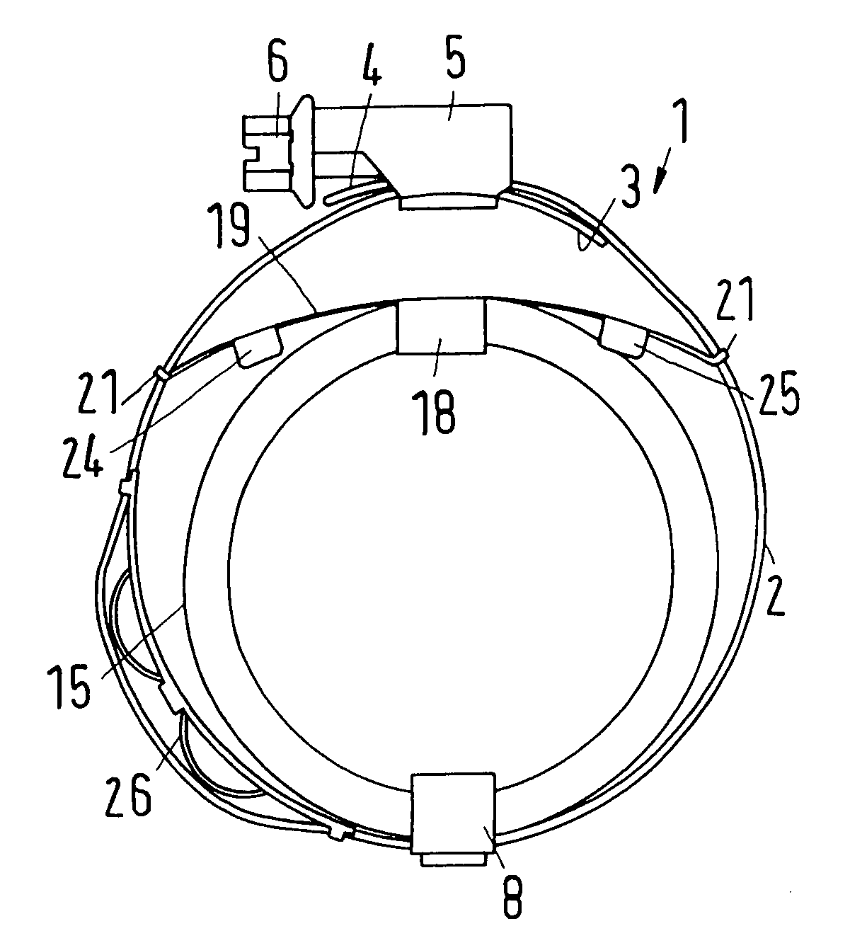
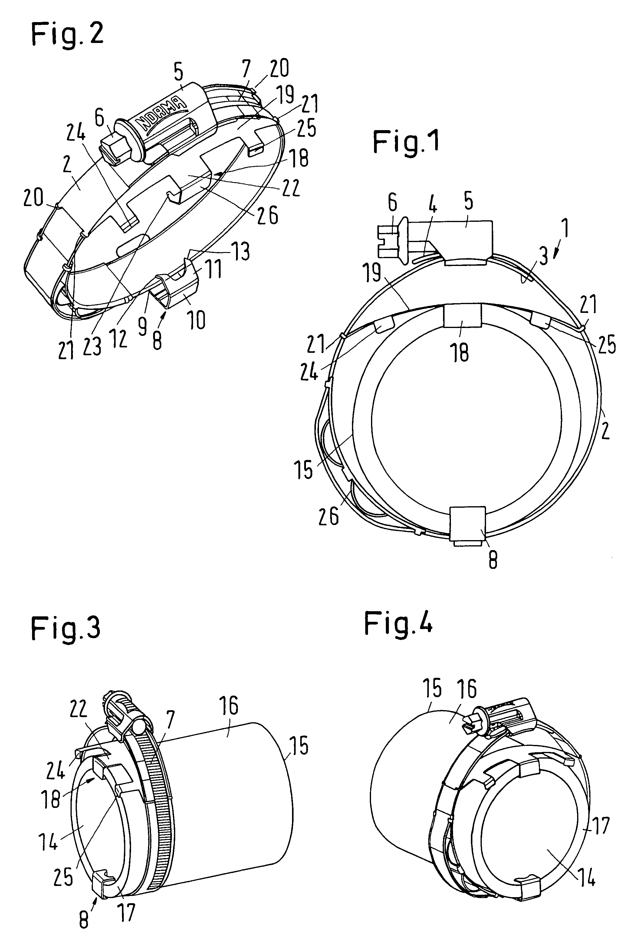
[0025]The hose clamp 1 shown in the drawings includes a clamping band 2 whose ends are placed one on top of the other in such a way that there is an inner end 3 and an outer end 4. The two ends 3, 4 are connected to each other through a clamping device 5. The clamping device 5 is fixedly connected to the inner end 3 of the clamping band and includes a clamping screw 6 which is in engagement with a threaded embossment 7 on the outer side of the outer end 4 of the clamping band. By rotating the tightening screw, the outer end 4 is displaced in the circumferential direction relative to the inner end 3 of the clamping band 2.

[0026]Diametrically oppositely arranged of the clamping device 5 is a first positioner 8 which is connected fixedly to the clamping band 2. The positioner may be welded or glued to the clamping band 2, or may be connected by clinching or embossing the clamping band 2. It is also possible to construct the first positioner 8 in a single piece with the clamping band 2....


PUM


Abstract

A hose clamp includes a clamping band, a tensioning device and a positioning arrangement for positioning the hose clamp on a hose. The positioning arrangement includes at least two positioners. The two positioners may be arranged at a distance from each other in a circumferential direction of at least 120°. Axial stops may be arranged on both sides in a circumferential direction of at least one of the positioners.

Description

BACKGROUND OF THE INVENTION[0001]1. Field of the Invention[0002]The present invention relates to a hose clamp with a clamping band, a clamping device and a positioning arrangement for positioning the hose clamp on a hose.[0003]2. Description of the Related Art[0004]A hose clamp of this type is known, for example, from WO 2004 / 044474A1. The positioning arrangement includes a positioner which is attached to the clamping band or is integrally formed in one piece with the clamping band. The positioner has two claw-like protrusions which can be pressed into the circumferential wall of a hose.[0005]A hose clamp has the primary purpose of fastening the end of a hose on a connection piece. The hose is pushed onto the connection piece and the hose clamp, which advantageously has already been mounted on the hose before the hose is pushed onto the connection piece, is tensioned by actuating the tensioning device. This procedure has to be repeated relatively frequently in the manufacture of an ...

Claims


Application Information

Patent Timeline
Patent Type & Authority Patents(United States)
IPC IPC(8): F16L33/04A44B99/00
CPCF16L33/08Y10T24/1484Y10T24/1441Y10T24/1457Y10T24/1412
Inventor KRAUSS, MATHIASMANN, STEPHANRODER, GUNTERKRIEGER, EWALD
Owner NORMA GERMANY GMBH
Why Eureka
Try Eureka