Internal tube for vacuum insulated glass (VIG) unit evacuation and hermetic sealing, vig unit including internal tube, and associated methods

a technology of vacuum insulation glass and internal tubes, applied in the field of vacuum insulation glass (vig) units, can solve the problems of air leakage, difficult to properly seal the pump-out tube, and the pump-out tube may not be properly seated, so as to simplify the manufacturing process, shipping, handling, transportation and/or other processing operations, and the effect of less car

Inactive Publication Date: 2020-07-09
GUARDIAN GLASS LLC
View PDF3 Cites 0 Cited by
  • Summary
  • Abstract
  • Description
  • Claims
  • Application Information

AI Technical Summary

Benefits of technology

[0012]This conventional arrangement is shown more fully in FIG. 3, which is a cross-sectional schematic view of a VIG unit having a sealed pump-out tube 8 that protrudes outwardly from the VIG unit and is protected using a cap 15. When evacuating and subsequently sealing the VIG unit, the pump-out port is used to allow an evacuation path. Conventionally, this port is sealed by inserting a tube 8 with frit 9 applied thereon into a hole drilled in the glass 2, firing the frit 9 around the hole, sealing the frit 9 in place, and sealing the tube 8 by melting it with a laser, resistive filament, or similar focused energy source, thereby hermetically sealing the VIG unit. A protective cap 15 is attached to the glass surface via adhesive tape 16 or other means to help protect the delicate tube 8 that protrudes from the glass surface.
[0013]Thus, it will be appreciated that it would be desirable to completely eliminate the need for a pump-out tube that protrudes outwardly from an outmost surface of the VIG unit and / or the cap therefor.
[0014]One aspect of certain example embodiments relates to the use of a pump-out tube internal to the VIG unit. In certain example embodiments, there is no need for a pump-out tube that protrudes outwardly from an outmost surface of the VIG unit. This arrangement in certain example instances simplifies the manufacturing process, e.g., by removing the need to provide and seal a separate cap, making shipping, handling, transportation, and / or other processing operations easier because less care has to be taken by virtue of the elimination of a critical through very fragile element of the VIG unit. Frame design, lamination, IG construction, and / or the like also can be simplified.
[0015]Another aspect of certain example embodiments relates to the sealing of the internal pump-out tube such that the sealed tube does not protrude past an outermost surface of (e.g., is flush with or lies within) the VIG unit. This arrangement is advantageous in certain example instances because it can reduce and sometimes eliminate the need for a separate protruding protective cap placed above the tube. The removal of the protective cap, in turn, can be advantageous from an aesthetic perspective. Moreover, the removal of the protective cap can be advantageous in terms of reducing the likelihood of damage to the VIG unit and making shipping, handling, transportation, and / or other processing operations easier. With respect to the former, as alluded to above, bumping the cap can translate force to the sealed tube, which can cause it to move and / or break, compromising the quality of the vacuum of the VIG. With respect to the latter, because the cap is missing, it may be possible to avoid having to use special shipping and / or packaging materials that accommodate such caps.
[0016]In certain example embodiments, a method of making a vacuum insulating glass (VIG) unit is provided. First and second glass substrates are provided, with the second substrate including a hole formed therein, with the hole being formed to have first and second portions, with the first portion being closer to an outer surface of the second substrate than the second portion, with the first portion having a first width across the second substrate and the second portion having a second width across the second substrate, and with the first width being narrower than the second width, the first and second portions together forming a through-hole through the second substrate. A pump-out tube is placed in the hole. The first and second substrates are sealed together in connection with an edge seal provided around peripheral edges of the first and / or second substrates, with a cavity being defined by the first and second substrates, and with a plurality of spacers being provided between the first and second substrates in the cavity and helping to maintain the first and second substrates in substantially parallel, spaced-apart relation to one another. The cavity is evacuated to a pressure less than atmospheric. The pump-out tube is heated so as to cause a portion of tube proximate to the first substrate to collapse inwardly upon itself, covering the second width and hermetically sealing the VIG unit and forming a sealed tube, with the sealed tube being completely internal to the VIG unit.
[0017]In certain example embodiments, a method of making a vacuum insulating glass (VIG) unit subassembly is provided. A second glass substrate is provided, with the second substrate including a hole formed therein, with the hole being formed to have first and second portions, with the first portion being closer to an outer surface of the second substrate than the second portion, with the first portion having a first width across the second substrate and the second portion having a second width across the second substrate, with the first width being narrower than the second width, and with the first and second portions together forming a through-hole through the second substrate. The second substrate is forwarded to another party to: place a pump-out tube in the hole; seal together a first glass substrate with the second substrates in connection with an edge seal provided around peripheral edges of the first and / or second substrates, a cavity being defined by the first and second substrates, and a plurality of spacers being provided between the first and second substrates in the cavity and helping to maintain the first and second substrates in substantially parallel, spaced-apart relation to one another; evacuate the cavity to a pressure less than atmospheric; and laser heat the pump-out tube so as to cause a portion of tube proximate to the first substrate to collapse inwardly upon itself, covering the second width and hermetically sealing the VIG unit and forming a sealed tube, the sealed tube being completely internal to the VIG unit.

Problems solved by technology

It sometimes may be the case that the pump-out tube may not be properly seated in the hole formed in the glass substrate.
As a result, in situations where the pump-out tube is improperly seated and is at an undesirable angle with respect to the surface of the glass substrate, it can become difficult to properly seal the pump-out tube because the laser cannot consistently melt the tip of the pump-out tube because of, for example, differences in distance between various portions of the angled pump-out tube top and the laser source.
Inconsistent melting of the top of the pump-out tube may result in incomplete sealing and thus air leakage, which may, depending on the quality of the seal, occur rapidly or more slowly over time.
If the laser hits the tube wall, the laser could potentially bypass the tube and hit the frit, which may damage the frit or cause undesirable outgassing into the cavity.
If the sealed tube is jostled, knocked loose, or broken in whole or in part, the VIG unit may lose vacuum faster than otherwise would be desirable.
Caps sometimes are provided over protruding sealed tubes to help protect against shocks that might cause breakage and the like, but such caps have a limited effectiveness against heavy mechanical forces and add additional processing steps and materials to the VIG unit manufacturing process.
With respect to the former, as alluded to above, bumping the cap can translate force to the sealed tube, which can cause it to move and / or break, compromising the quality of the vacuum of the VIG.

Method used


Image

  • Internal tube for vacuum insulated glass (VIG) unit evacuation and hermetic sealing, vig unit including internal tube, and associated methods
  • Internal tube for vacuum insulated glass (VIG) unit evacuation and hermetic sealing, vig unit including internal tube, and associated methods
  • Internal tube for vacuum insulated glass (VIG) unit evacuation and hermetic sealing, vig unit including internal tube, and associated methods

Examples


Embodiment Construction

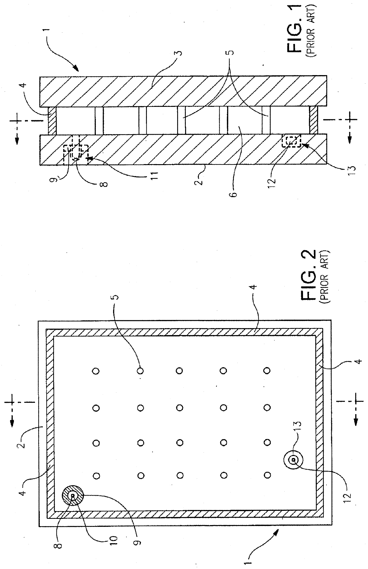
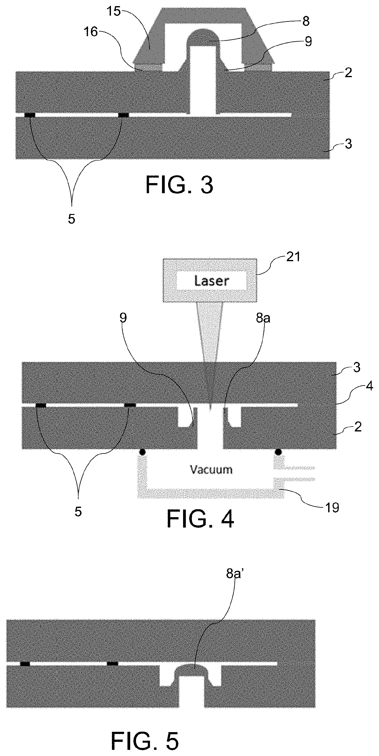
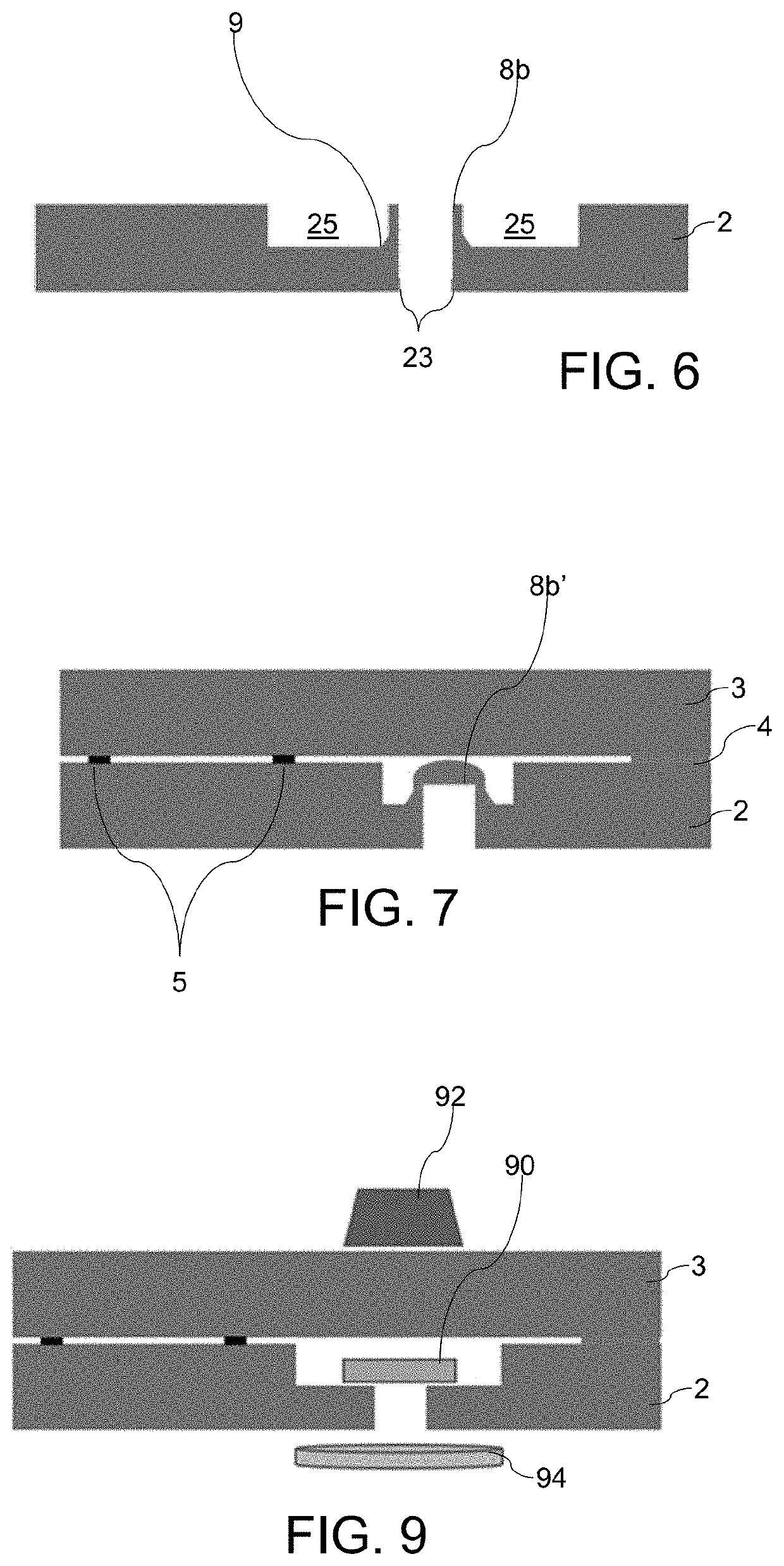
[0033]Certain example embodiments relate to improved techniques for evacuating vacuum insulated glass (VIG) units. More particularly, certain example embodiments of this invention relate to an internal pump-out tube for VIG unit evacuation and hermetic sealing, a VIG unit subassembly including an internal pump-out tube, a VIG unit made using an internal pump-out tube, and / or associated methods. Typically, the internal space of a VIG unit is evacuated through a surface mounted tube or other structure that facilitates sealing once the internal space reaches sufficiently low pressures. That tube or other structure protrudes from the surface even when sealed and typically is protected with a protective cap but nonetheless oftentimes requires special handling. Certain example embodiments improve upon this approach by relocating the sealing tube to within the VIG unit, thereby potentially eliminating the need for a protective cap and allowing for more freedom in handling, frame design, hy...


PUM

PropertyMeasurementUnit
pressureaaaaaaaaaa
diameteraaaaaaaaaa
diameteraaaaaaaaaa

Abstract

Certain example embodiments of this invention relate to vacuum insulated glass (VIG) units, and/or methods of making the same. The sealing tube or sealing material is provided within the VIG unit, thereby potentially eliminating the need for a protective cap and allowing for more freedom in handling, frame design, hybrid VIG construction, lamination, and the like. The sealing tube may be relocated to an internal area within a recessed pocket of a substrate at least in certain example embodiments. The VIG unit lacks a protruding pump-out tube or the like.

Description

TECHNICAL FIELD[0001]Certain example embodiments of this invention relate to vacuum insulated glass (VIG) units, and / or methods of making the same. More particularly, certain example embodiments of this invention relate to an internal pump-out tube for VIG unit evacuation and hermetic sealing, a VIG unit subassembly including an internal pump-out tube, a VIG unit made using an internal pump-out tube, and / or associated methods.BACKGROUND AND SUMMARY[0002]Vacuum insulating glass (VIG) units typically include at least two spaced apart glass substrates that enclose an evacuated or low-pressure space / cavity therebetween. The substrates are interconnected by a peripheral edge seal and typically include spacers between the glass substrates to maintain spacing between the glass substrates and to avoid collapse of the glass substrates that may be caused due to the low pressure environment that exists between the substrates. Some example VIG configurations are disclosed, for example, in U.S. ...

Claims


Application Information

Patent Timeline
Patent Type & Authority Applications(United States)
IPC IPC(8): E06B3/66E06B3/663E06B3/677
CPCE06B3/6775E06B3/6612E06B3/66304E06B3/677Y02A30/249Y02B80/22
Inventor HOGAN, JOHN P.
Owner GUARDIAN GLASS LLC
Why Eureka
Try Eureka