

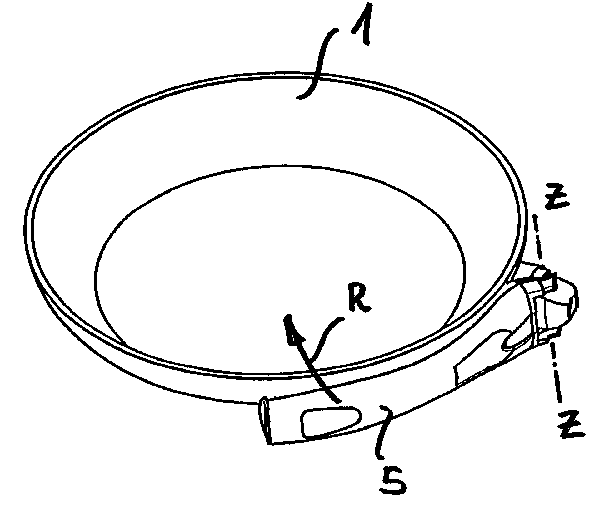
Tilting handle for pans
a technology for tilting and pans, which is applied in the field of tilting pans, can solve the problems of large space required and drawbacks of using such a removable handle, and achieve the effect of reducing the size of the pan and being easy to grip and sa
- Summary
- Abstract
- Description
- Claims
- Application Information
AI Technical Summary
Benefits of technology
Problems solved by technology
Method used
Image

Examples
Embodiment Construction
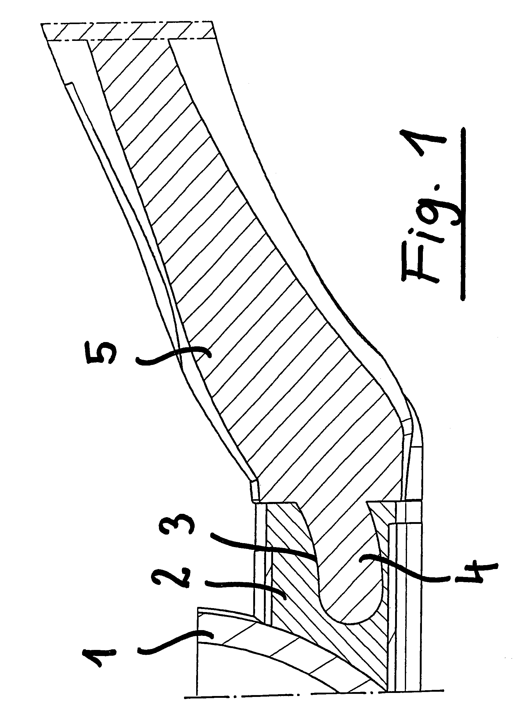
[0019]FIG. 1 shows in cross section a portion of the cooking pan 1 from which projects a supporting extension 2 including a plurality of parallel openings 3 for engaging therein corresponding projections 4 projecting from a handle 5.
[0020]This detail will be further disclosed hereinafter.
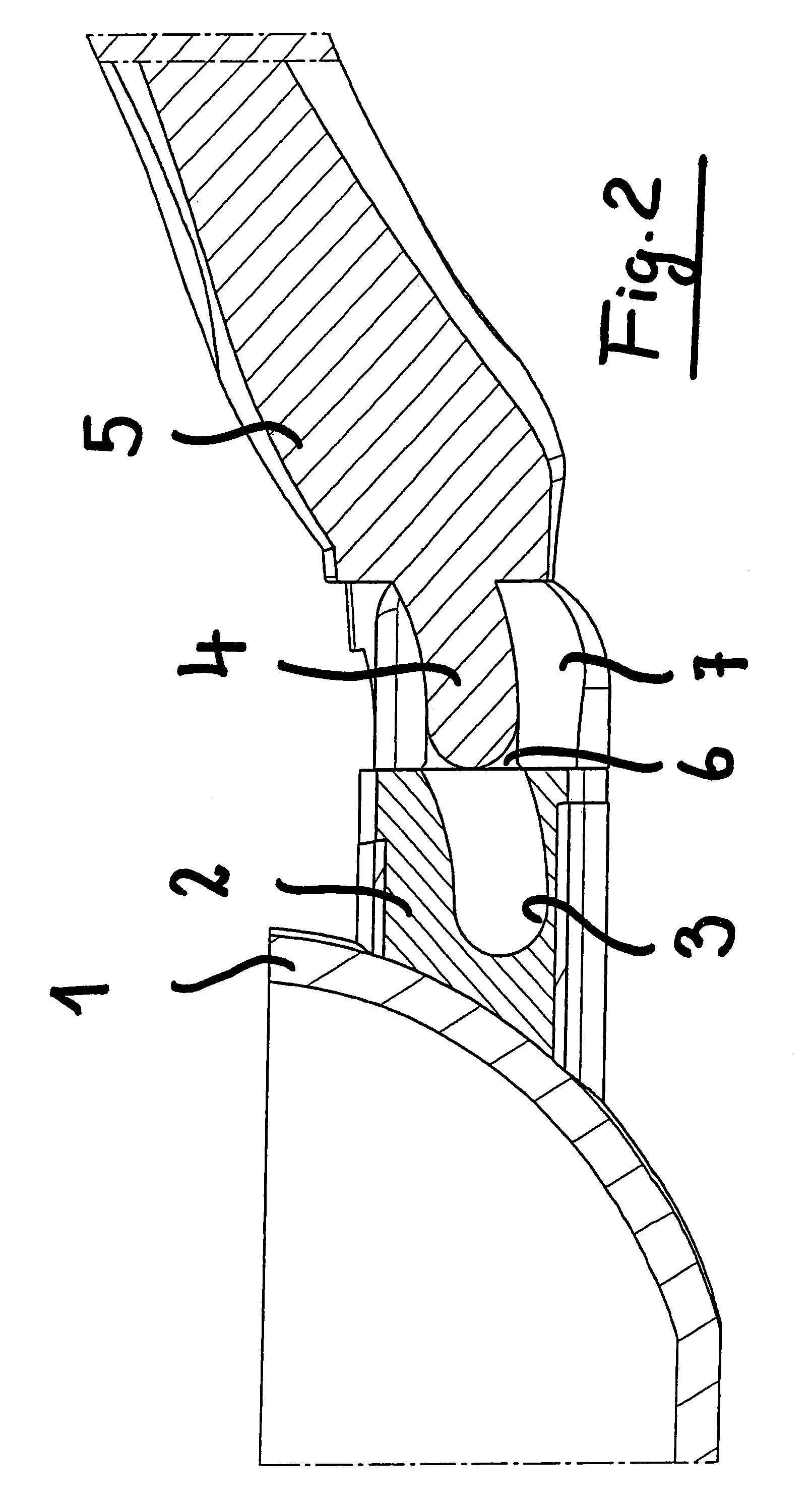
[0021]FIG. 2 schematically shows a portion of the pan 1 and projecting support 2, a cavity 3 and projection 4 or handle arm 5, exiting a corresponding cavity 3.
[0022]Each projection 4 is also guided in an extension 6 of the cavity 3, which extension is formed in a supporting body 7 which can be turned with respect to the support 2 about a horizontal axis X.
[0023]FIG. 3 shows, in cross section, a portion of the pan 1 with the projecting support 2 and the projection 7, coupled to said support 2 by a coupling screw 8.
[0024]FIG. 3 shows moreover, in cross section, a portion of the handle 5 receiving a locking tilting lever 9 which may swing or tilt about a cross pin 10.
[0025]Said lever 9 has an end ther...
PUM
 Abstract
Description
Claims
Application Information