Lift and moveable underride

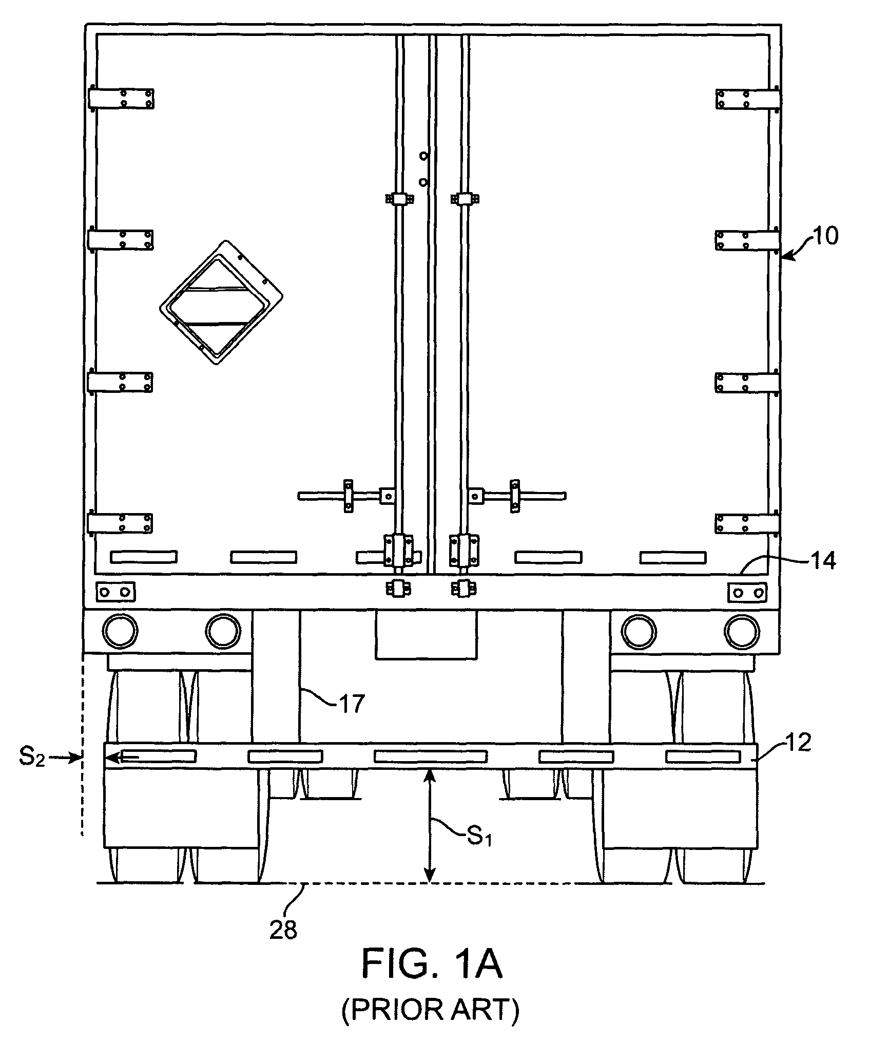
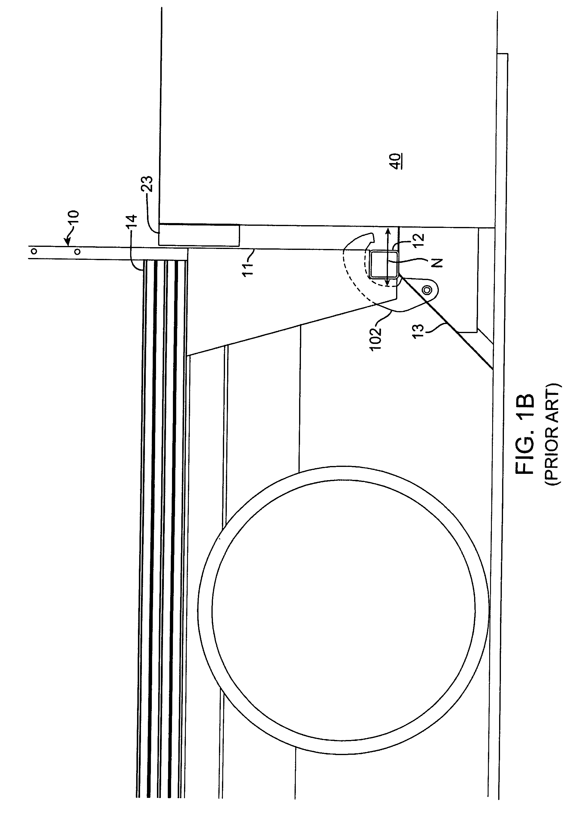
a technology of underride and lift, which is applied in the direction of transportation items, loading/unloading vehicle arrangment, and refuse collection, etc., can solve the problem that underride b>12/b> is not compatible with a li

Active Publication Date: 2010-07-27
MAXON INDS INC
View PDF4 Cites 30 Cited by
  • Summary
  • Abstract
  • Description
  • Claims
  • Application Information

AI Technical Summary

Problems solved by technology

As a result, such an underride 12 is not compatible with a lift that is stowed under the rear end of the vehicle since the underride 12 interferes with the stowing and unstowing of the lift.

Method used


Image

  • Lift and moveable underride
  • Lift and moveable underride
  • Lift and moveable underride

Examples


Embodiment Construction

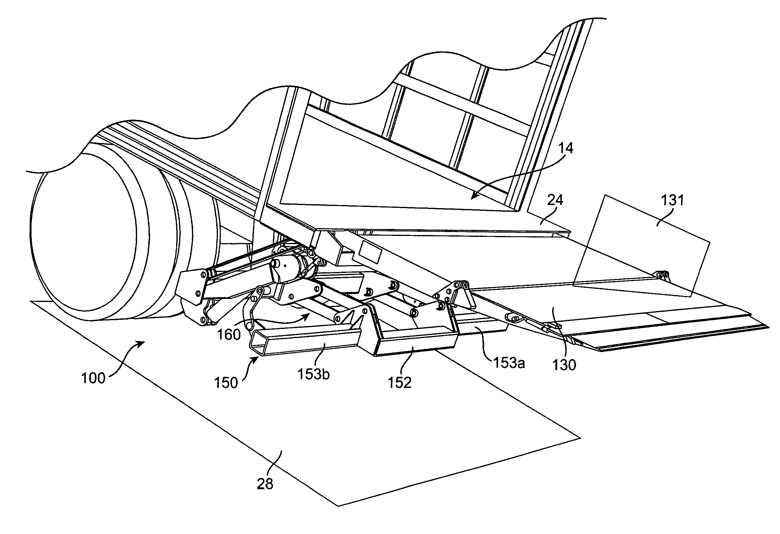
[0036]The invention provides a moveable underride system that may be used with lifts such as stow lifts (tuck under lifts). In one embodiment the invention provides an underride member and a linkage mechanism for coupling the underride member to a frame, wherein the linkage mechanism moves the underride member between an extended position and a retracted position. In the extended position the underride member is at a first distance from the frame, and in the retracted position the underride is at a second distance from the frame, such that the first distance (for the extended position) is larger than the second distance (for the retracted position). When the underride system is coupled to a rear frame of a vehicle such as a truck or a trailer, the extended position of the underride member allows at least a portion of the underride member to be engaged by a dock lock of a docking station.

[0037]In another embodiment the invention provides a lift system configured for use with a vehicl...


PUM


Abstract

The invention provides a moveable underride system that may be used with lifts such as stow lifts. The underride system includes an underride member and a linkage mechanism for coupling the underride member to a support frame, wherein the linkage mechanism moves the underride member between an extended position and a retracted position. In the extended position the underride member is at a first distance from the frame, and in the retracted position the underride is at a second distance from the frame, such that the first distance (for the extended position) is larger than the second distance (for the retracted position).

Description

CROSS-REFERENCE TO RELATED APPLICATIONS[0001]The present application claims priority under 35 USC section 119(e) to U.S. Provisional Application No. 60 / 871,299, filed on Dec. 21, 2006, the disclosure of which is hereby incorporated by reference in its entirety.BACKGROUND OF THE INVENTION[0002]1. Field of the Invention[0003]The present invention relates generally to vehicle rear impact guards, and in particular to rear impact guards used with lifts and dock locks.[0004]2. Description of Related Art[0005]Rear impact guards, or commonly known as underrides, are used to reduce the chance of following vehicles from driving underneath the bed of a vehicle such as a truck or a trailer. FIG. 1A shows a rear view of a vehicle 10, such as a conventional truck or trailer, with a fixed horizontal underride 12 (relative to ground level 28), installed below the vehicle bed 14 via vertical beams 17. As shown in the side view of the vehicle 10 in FIG. 1B, the underride 12 is positioned under the en...

Claims


Application Information

Patent Timeline
Patent Type & Authority Patents(United States)
IPC IPC(8): B60P1/44
CPCB60P1/445B60P1/4485
Inventor ABLABUTYAN, KARAPETGASPARIAN, AKOP
Owner MAXON INDS INC
Why Eureka
Try Eureka