Downhole navigation and detection system

a detection system and navigation system technology, applied in the field of oil and gas well logging tools, can solve the problems of bulky insulation, difficult signal passing between the tool and the reservoir, and high voltage of the photomultiplier tube,

Inactive Publication Date: 2010-07-27
BAKER HUGHES INC
View PDF25 Cites 25 Cited by
  • Summary
  • Abstract
  • Description
  • Claims
  • Application Information

AI Technical Summary

Problems solved by technology

However, once a well has been cased, there exists a layer of steel and concrete between the interior of the wellbore where the tool is located and the formation itself.
The well casing makes it difficult for signals to pass between the tool and the reservoir and vice-versa.
Firstly, photomultiplier tubes require high voltages.
The high voltage means that bulky insulation has to be provided.
Photomultiplier tubes are inherently bulky, a disadvantage for downhole applications where space is at a premium.
Their output can become noisy at the elevated temperatures encountered in boreholes.
In order to reduce the effects of elevated temperatures, Dewar flasks may be used to keep the temperature down—another operational disadvantage.
The noise becomes worse as the photomultiplier tube ages and has been exposed to long periods of vibration.
Photomultiplier tubes can be damaged by vibration and the harsh conditions encountered downhole.

Method used


Image

  • Downhole navigation and detection system
  • Downhole navigation and detection system
  • Downhole navigation and detection system

Examples


Embodiment Construction

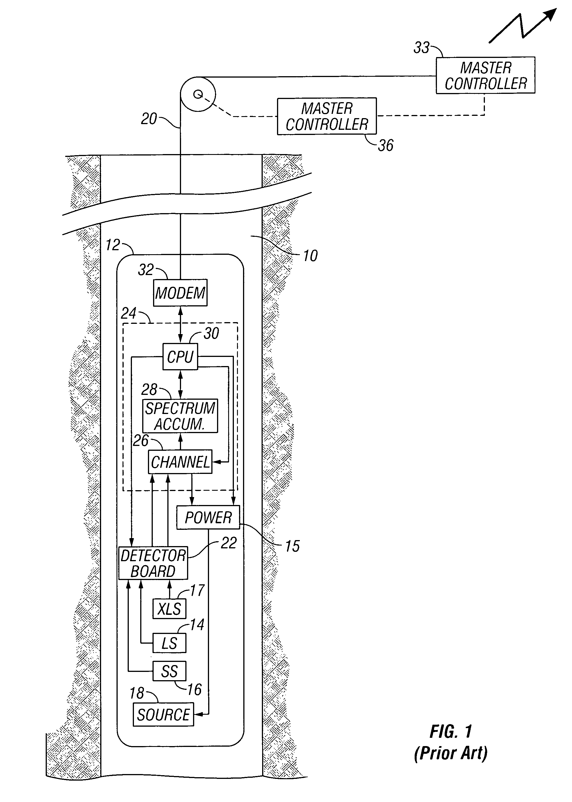
[0024]The system shown in FIG. 1 is an exemplary prior art system for density logging. Well 10 penetrates the earth's surface and may or may not be cased depending upon the particular well being investigated. It is a wireline system. This is not a limitation of the invention as the method of the invention is applicable to MWD systems and an MWD implementation of the apparatus may be done. Disposed within well 10 is subsurface well logging instrument 12. The system diagramed in FIG. 1 is a microprocessor-based nuclear well logging system using multi-channel scale analysis for determining the timing distributions of the detected gamma rays. Well logging instrument 12 includes an extra-long spaced (XLS) detector 17, a long-spaced (LS) detector 14, a short-spaced (SS) detector 16 and pulsed neutron source 18. In one embodiment of the invention, XLS, LS and SS detectors 17, 14 and 16 are comprised of bismuth-germanate (BGO) crystals coupled to photomultiplier tubes. To protect the detect...


PUM


Abstract

A photodiode whose long-wavelength cutoff is in the short-wavelength range (preferably, between ultraviolet and yellowish-green) having reduced temperature sensitivity is used in downhole applications. It may be matched with scintillation devices having an output matched to the response curve of the photodiode for use with nuclear logging devices. The photodiode may also be used in gyroscopes in which light from an LED matched to the photodiode is reflected from a spinning mass.

Description

CROSS-REFERENCES TO RELATED APPLICATIONS[0001]This application claims priority from U.S. Provisional Patent Application Ser. No. 60 / 708,330 filed on 15 Aug. 2005.BACKGROUND OF THE INVENTION[0002]This invention relates generally to oil and gas well logging tools. More particularly, this invention relates tools for measuring rock formation properties such as density and porosity. This invention relates to an improved density tool using radiation detectors with improved operating characteristics at high temperatures that may be used in cased holes as well as open holes.[0003]In petroleum and hydrocarbon production, it is desirable to know the porosity and density of the subterranean formation which contains the hydrocarbon reserves. Knowledge of porosity is essential in calculating the oil saturation and thus the volume of oil in-place within the reservoir. Knowledge of porosity is particularly useful in older oil wells where porosity information is either insufficient or nonexistent t...

Claims


Application Information

Patent Timeline
Patent Type & Authority Patents(United States)
IPC IPC(8): G01V5/08
CPCE21B47/024G01V5/101G01V5/107
Inventor ESTES, ROBERT A.DIFOGGIO, ROCCOMOLZ, ERIC B.CHALITSIOS, CONSTANTYNKURKOSKI, PHILIP L.
Owner BAKER HUGHES INC
Why Eureka
Try Eureka