Lay-in lug nut plate retainer

a technology of nut plate retainer and lug, which is applied in the field of lugs, can solve problems such as particularly probable and problemati

Active Publication Date: 2010-08-03
SIEMENS IND INC
View PDF31 Cites 18 Cited by
  • Summary
  • Abstract
  • Description
  • Claims
  • Application Information

AI Technical Summary

Benefits of technology

[0013]A lay-in lug has two spaced apart and substantially parallel lug walls. A nut plate is supported between the first lug wall and the second lug wall. A plate retainer exerts force on a lug wall and restricts the plate from moving in a direction substantially parallel to the first and second lug walls. The plate retainer has a flexible retaining base and a pair of retaining legs extending from the retaining base. Snap protrusions extend from each of the retaining legs and are formed to interlock with a portion of the wall of the lay-in lug and restrict movement the nut plate. The plate retainer either snaps around the edge of the lug wall or along the wall's length. It may also clip around the nut plate and prevents its movement in a direction along the inner surfaces of the lug walls.

Problems solved by technology

This is especially probable and problematic during the aforementioned electrical conduit riser type installation.

Method used


Image

  • Lay-in lug nut plate retainer
  • Lay-in lug nut plate retainer
  • Lay-in lug nut plate retainer

Examples


Embodiment Construction

[0023]The present invention generally provides apparatus for securing nut plates in lay-in lugs.

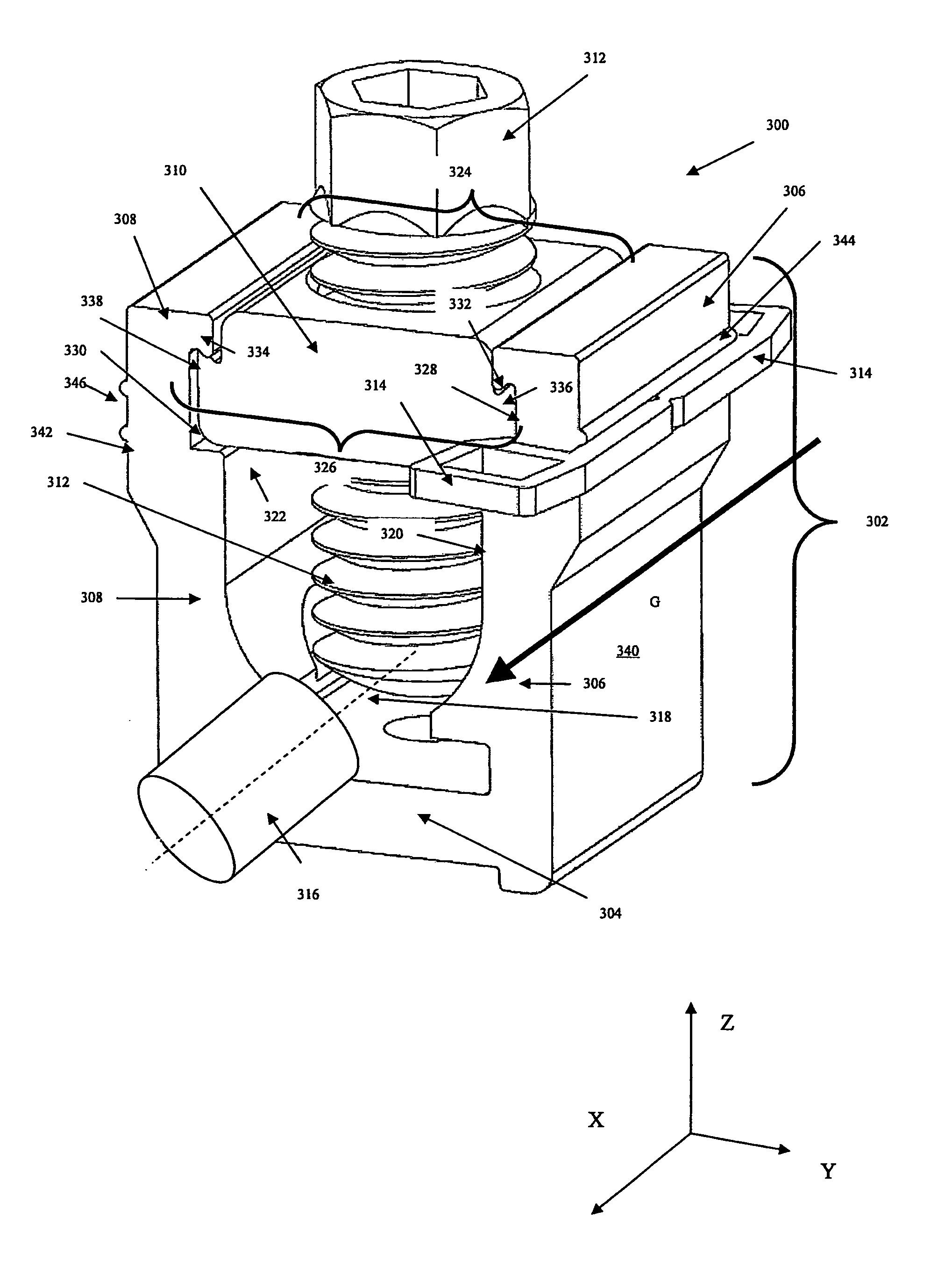
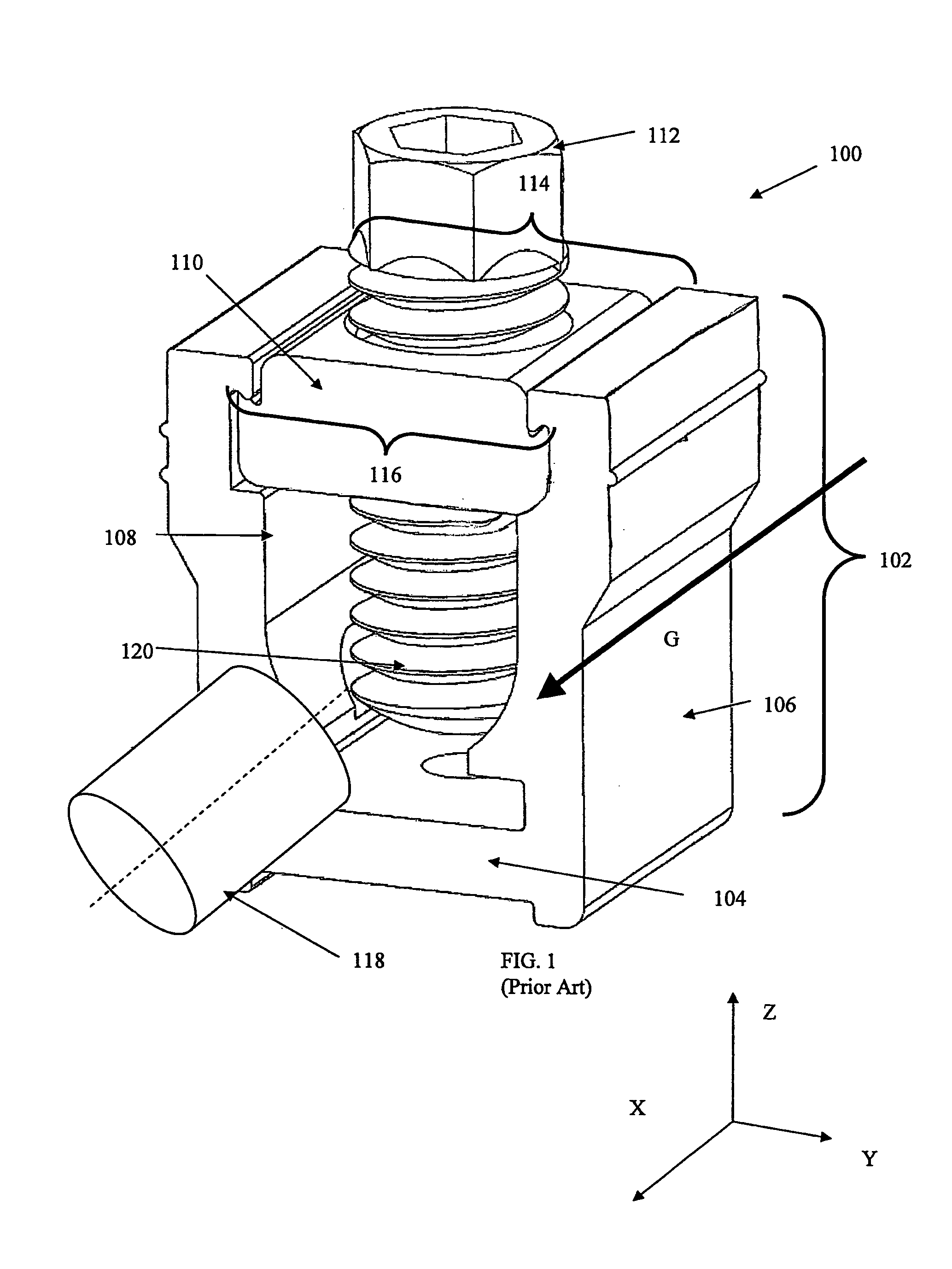
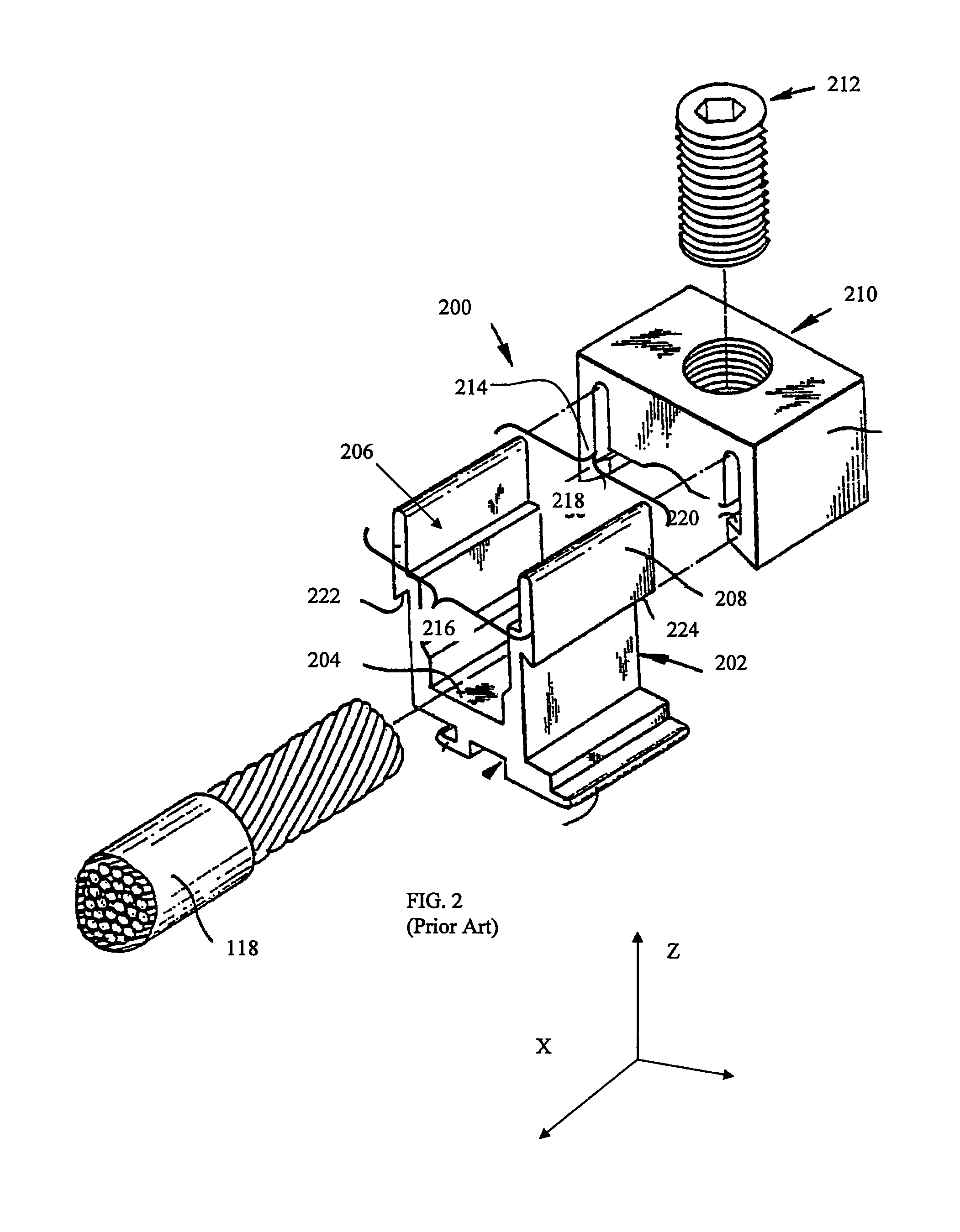
[0024]FIGS. 3-6 depict a lay-in lug 300 according to an embodiment of the present invention. Lay-in lug 300 may be similar to and improve on lay-in lugs 100 and 200 of FIGS. 1 and 2. Accordingly, similar features are not described in further detail except as necessary to elucidate embodiments of the present invention.

[0025]FIG. 3 is a front perspective view of lay-in lug 300. FIG. 4 is a top view of lay-in lug 300. FIG. 5 is top-front perspective view of lay-in lug 300. FIG. 6 is a side-front perspective view of lay-in lug 300.

[0026]Lay-in lug 300 has a lug body 302 comprising a base 304 and two opposed and substantially parallel vertical lug walls 306, 308. Supported between and / or atop lug walls 306 and 308 is a removable nut plate 310, which secures a wire binding screw 312. A plate retainer 314 restricts nut plate 310 from moving in direction along lug walls 306, 308 (e.g., along the ...


PUM


Abstract

A lay-in lug has two spaced apart and substantially parallel lug walls. A nut plate is supported between the first lug wall and the second lug wall. A plate retainer exerts force on a lug wall and restricts the plate from moving in a direction substantially parallel to the first and second lug walls. The plate retainer has a flexible retaining base and a pair of retaining legs extending from the retaining base. Snap protrusions extend from each of the retaining legs and are formed to interlock with a portion of the wall of the lay-in lug and restrict movement the nut plate. The plate retainer either snaps around the edge of the lug wall or along the wall's length. It may also clip around the nut plate and prevents its movement in a direction along the inner surfaces of the lug walls.

Description

[0001]This application claims the benefit of U.S. Provisional Application No. 60 / 955,982 filed Aug. 15, 2007, which is incorporated herein by reference.BACKGROUND OF THE INVENTION[0002]The present invention relates generally to lay-in lugs and more particularly to techniques for securing a nut plate of a lay-in lug.[0003]Lay-in lugs are similar to “C” or “J” type lugs, as are known, and are used to secure wires (e.g., electrical cables, wiring, tubing, etc.). Lay-in lugs are often used in electrical and similar applications to electrically connect service and / or feed phase-neutral conductors to electrical metering equipment and / or circuit protection. Lay-in lugs may be used in piping systems, such as electrical conduits and the like, to secure wires transposed vertically in a shaft, such as an electrical conduit riser. That is, lay-in lugs are used to hold (e.g., hang) wires vertically.[0004]FIG. 1 is a front perspective view of an exemplary lay-in lug 100 as is known. Lay-in lug 10...

Claims


Application Information

Patent Timeline
Patent Type & Authority Patents(United States)
IPC IPC(8): H01R4/36
CPCH01R4/36H01R43/00
Inventor ROBINSON, KRISTOPHER SCOTTTIRRELL, JAMES R.RUSCH, BRIAN J.
Owner SIEMENS IND INC
Why Eureka
Try Eureka