V-belt continuously variable transmission and straddle-type vehicle

a technology of v-belt and transmission, which is applied in the direction of guards, cycle equipment, gears, etc., can solve the problems that the installation method of electric motors and rotational speed sensors used in v-belt cvts of scooter-type motorcycles cannot be used in atvs, and achieve the effect of high responsiveness to the vehicle running condition

Active Publication Date: 2010-08-10
YAMAHA MOTOR CO LTD
View PDF18 Cites 33 Cited by
  • Summary
  • Abstract
  • Description
  • Claims
  • Application Information

AI Technical Summary

Benefits of technology

[0016]In order to overcome the problems described above, preferred embodiments of the present invention provide a compact, yet durable V-belt CVT and straddle-type vehicle achieving a speed change operation that is highly responsive to the vehicle running condition.
[0026]In the V-belt CVT constructed as described above, the rotational speed sensor for detecting the rotational speed of the primary sheave shaft and the secondary sheave is disposed on a portion of the primary sheave shaft, to a first end of which the driving force of the engine is input, toward a second end with respect to the primary sheave. In this way, the rotational speed sensor can be spaced away from the cylinder block of the engine which can be hot, and also, it is not necessary to ensure an installation space for the rotational speed sensor around the outer periphery of the primary sheave.
[0027]Thus, it is possible to obtain a compact, yet durable V-belt CVT achieving a speed change operation highly responsive to the engine operating condition.
[0028]In the straddle-type vehicle constructed as described above, the V-belt CVT of the present preferred embodiment is located below the seat and the rotational speed sensor is located above a horizontal plane including the primary sheave shaft. In this way, a projection toward a lateral side of the vehicle body due to the installation of the rotational speed sensor is arranged above the foot placed on the footrest and thus does not prevent the rider from putting his / her foot in place.
[0029]Thus, it is possible to provide a rotational speed sensor without sacrificing the possibility of a compact V-belt CVT located below the seat and without hindering the rider from putting his / her feet in place on both sides of the vehicle body, thereby achieving a straddle-type vehicle with a speed change operation that is highly responsive to the vehicle running condition.

Problems solved by technology

However, when the road on which the vehicle is running turns from a flat road to a climbing road, for example, the sheave drive mechanism of the centrifugal type does not perform a groove width control operation (specifically, a speed change operation) responsively according to changes in the road condition, irrespective of the intention of the rider, until the engine speed has actually decreased because of the increased load from the road.
That is, the sheave drive mechanism has a problem of delayed response.
However, since ATVs are significantly different in structure from scooter-type motorcycles, the installation method of an electric motor and a rotational speed sensor used in V-belt CVTs of scooter-type motorcycles cannot be used in ATVs.
Thus, it is not easy to ensure an installation space for the electric motor and the rotational speed sensor, even on the outer side of the vehicle body.
This is because the rotational speed sensor would project greatly to the outer side of the vehicle body and hence prevent the rider from putting his / her foot in place, thereby interfering with the usability of the ATV.
In the case where the rotational speed sensor is located around the outer periphery of the primary sheave or the secondary sheave, a transmission casing is increased in size and hence the V-belt CVT cannot be made compact.
In addition, in the case where the rotational speed sensor is installed near a heat producing part such as a cylinder block of the engine, the service life of the rotational speed sensor and / or the measurement accuracy of the sensor may be reduced and therefore the original performance cannot be maintained.

Method used


Image

  • V-belt continuously variable transmission and straddle-type vehicle
  • V-belt continuously variable transmission and straddle-type vehicle
  • V-belt continuously variable transmission and straddle-type vehicle

Examples


Embodiment Construction

[0039]Preferred embodiments of a V-belt continuously variable transmission (CVT) and a straddle-type vehicle according to the present invention will hereinafter be described in detail with reference to the accompanying drawings.

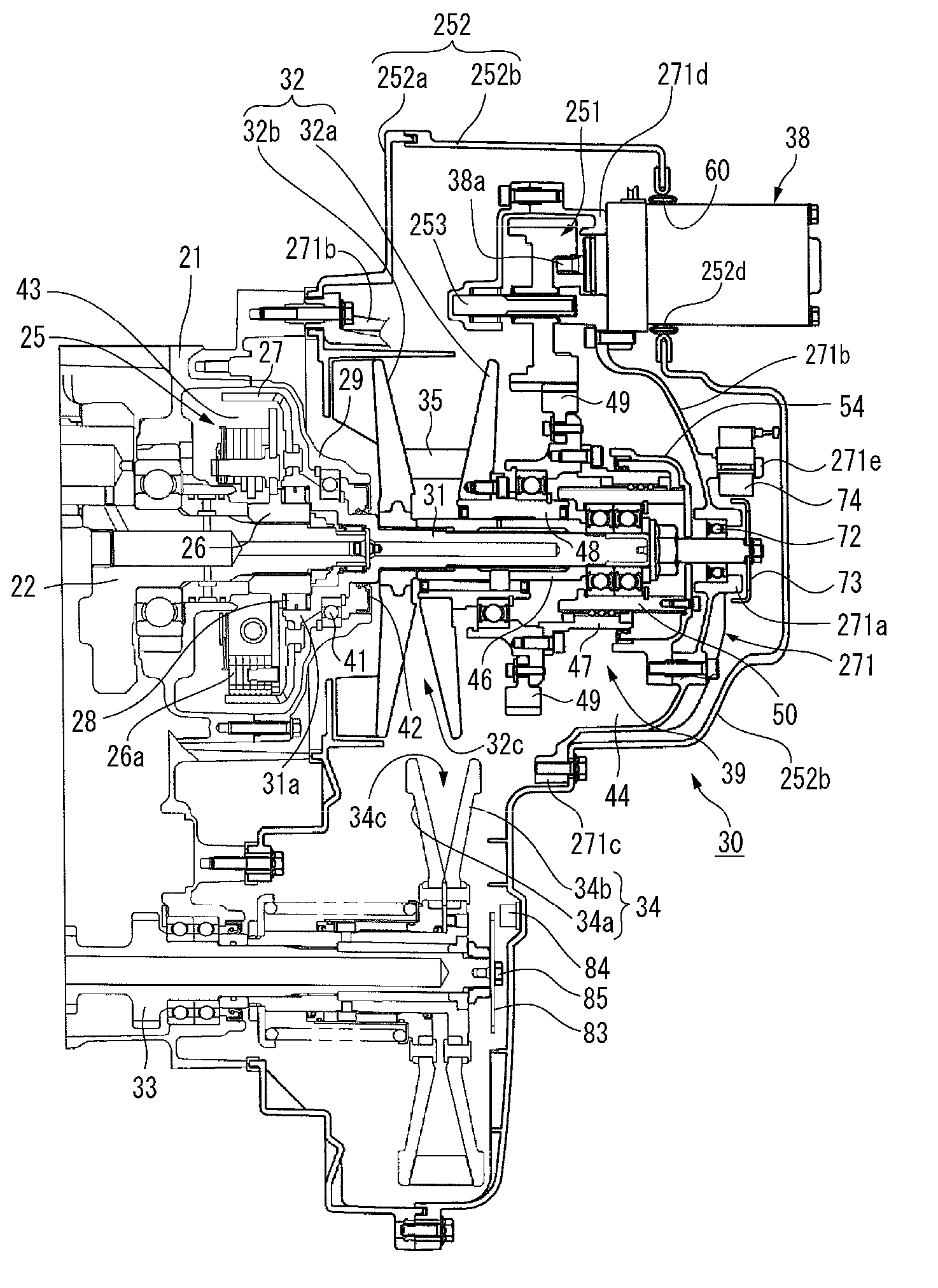
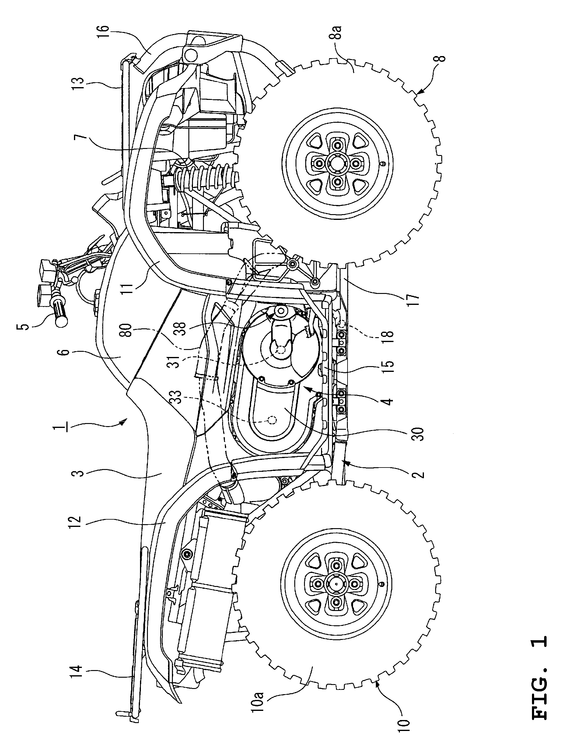
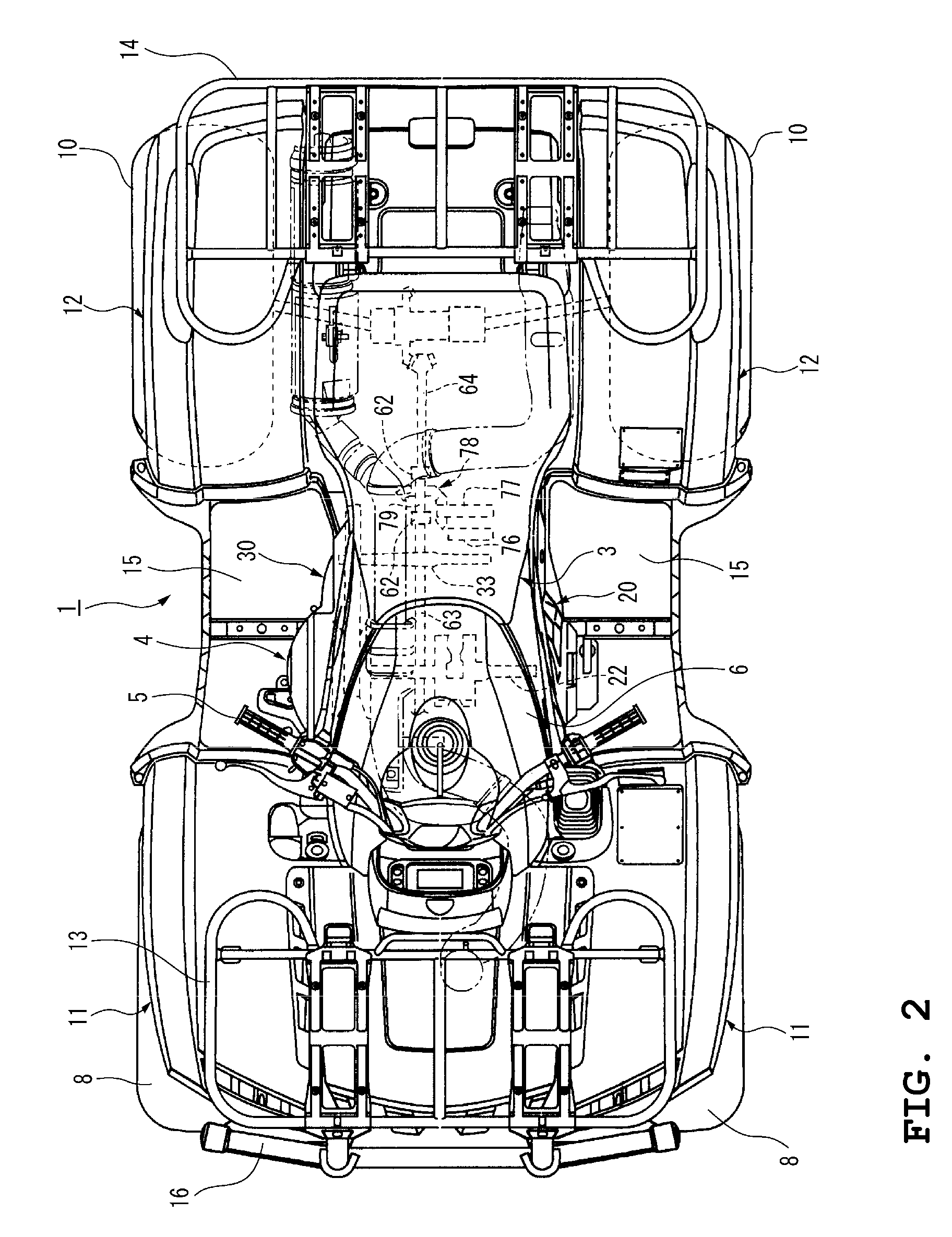
[0040]FIGS. 1 through 5 illustrate a straddle-type vehicle incorporating a V-belt CVT according to a first preferred embodiment of the present invention. FIG. 1 is a right side view of the straddle-type vehicle incorporating a power unit in which the V-belt CVT according to the first preferred embodiment of the present invention is assembled to an engine. FIG. 2 is a plan view of the straddle-type vehicle shown in FIG. 1. FIG. 3 is a right side view of the power unit mounted in the straddle-type vehicle shown in FIG. 1 with a cover of the V-belt CVT removed. FIG. 4 is a sectional view taken along the line A-A of FIG. 3. FIG. 5 is a right side view of the cover of the V-belt CVT shown in FIG. 1. In this specification, “left” and “right” refer to the left and r...


PUM


Abstract

A V-belt continuously variable transmission (CVT) for a straddle-type vehicle includes a measurement plate for a rotational speed sensor for detecting a rotational speed of a primary sheave shaft to control a speed change ratio. The measurement plate is disposed on an opposite end of the primary sheave shaft, to one end of which a driving force of an engine is input, with respect to a primary sheave.

Description

BACKGROUND OF THE INVENTION[0001]1. Field of the Invention[0002]The present invention relates to a V-belt continuously variable transmission (CVT) for transmitting a driving force of an engine to a driving wheel, and a straddle-type vehicle having such a V-belt CVT disposed below a seat of the vehicle.[0003]2. Description of the Related Art[0004]Recently, there is an increasing demand for straddle-type vehicles called “ATVs (all-terrain vehicles).”[0005]Also, there have been proposed various types of ATVs in which four wheels are provided, each wheel having a wide and low-pressure balloon tire or the like on the left and right sides of the front and rear sides of a body frame, the upper portion of the body frame is provided with steering handlebars, a fuel tank, and a straddle-type seat, arranged sequentially from the front wheel side to the rear wheel side, and a V-belt CVT disposed below the seat and for transmitting a driving force of an engine to driving wheels (see JP-A-2004-15...

Claims


Application Information

Patent Timeline
Patent Type & Authority Patents(United States)
IPC IPC(8): F16H61/00F16H59/00
CPCF16H9/18F16H63/062Y10S180/908
Inventor MOCHIZUKI, SHIGEHIROIZUMI, KAZUHIKO
Owner YAMAHA MOTOR CO LTD
Why Eureka
Try Eureka