
Oblique image stitching

a mosaic image and image technology, applied in the field of image stitching, can solve the problems of insufficient resolution for accurate texture mapping applications, too noisy lidar-based techniques, and confusion of artifacts, and achieve the effect of reducing artifacts

Active Publication Date: 2010-08-17
MICROSOFT TECH LICENSING LLC
View PDF19 Cites 51 Cited by
  • Summary
  • Abstract
  • Description
  • Claims
  • Application Information

AI Technical Summary

Benefits of technology

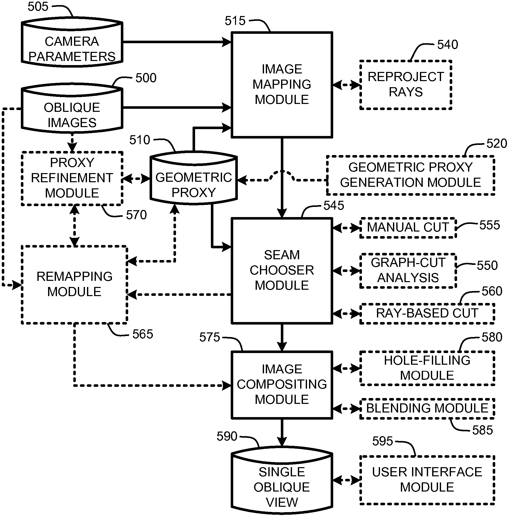
[0017]In general, the Oblique Image Stitcher first projects each input image onto the geometric proxy of the scene using conventional projective texture mapping techniques and then renders the scene from the desired viewpoint of the mosaic. Further, in one embodiment, the output mosaic viewpoint is an isometric, or oblique parallel, projection. One advantage to rendering from a parallel projection is that it allows for the creation of an arbitrarily large image that can be panned across, as desired. Note that in this case, the viewpoint of the mosaic can be chosen so the imaging rays of the output mosaic are as parallel as possible to the rays from the input perspective images to minimize the artifacts due to incorrect geometric proxies.

Problems solved by technology

However, buildings are not modeled by this approach, leading to confusing artifacts (especially with tall buildings) when viewing images from a different direction than the original images were taken from.
Unfortunately, LiDAR-based techniques tend to be too noisy, and provide insufficient resolution for accurate texture mapping applications.
Smoothing LiDAR models tends to be a difficult and computationally expensive problem.
Unfortunately regardless of the type of 3D model that is used, the problem of correctly aligning occlusion boundaries of buildings is not adequately addressed.
As a result, the images resulting from such schemes tend to include misaligned textures and mismatching shadows from one surface to another.
Further, mapping the mosaiced images to such models typically results in very unnatural angles and warping of objects such as buildings.
In other words, the resulting mosaic images do not provide photorealistic views of the scene.
However, the problem of photorealistic image stitching is more complicated in the case of oblique imagery, especially in the case of images of tall buildings captured at an angle from a moving airplane.
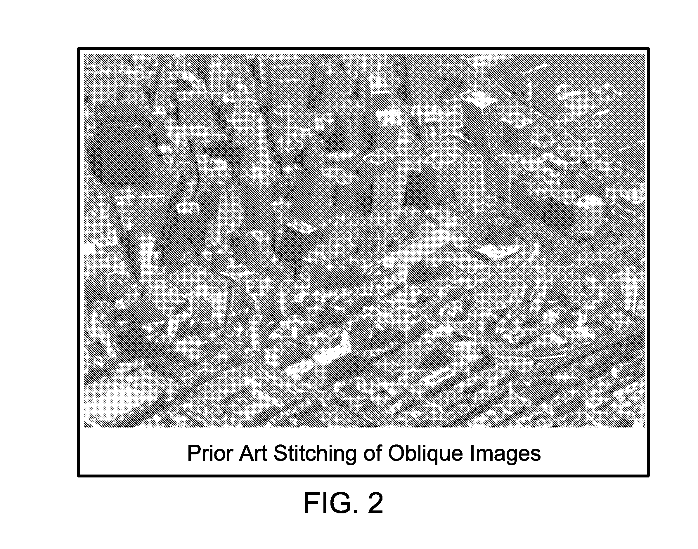
Unfortunately, the resulting mosaic image will tend to include a confusing jumble of tall buildings or other structures that all lean at different angles relative to each other because of the different oblique angles at which the various images were captured.
In other words, the resulting mosaic images do not provide photorealistic views of the scene.
However, as the depth information in such techniques corresponds to a set of view-parallel planes, slanted surfaces cannot be represented well and appear discretized.
Again, the result tends to be a mosaic image that fails to provide a photorealistic view of the scene.
Consequently, such schemes tend to fare poorly when addressing the problem of constructing a photorealistic view of the scene.
Consequently, with respect to mosaic images, the basic problem with the use of such oblique imagery is, given a set of partially overlapping views taken of a scene, looking down at some predetermined angle, to produce an “as-seamless-as-possible” oblique mosaic view of that scene.

Method used


Image

  • Oblique image stitching
  • Oblique image stitching
  • Oblique image stitching

Examples


Embodiment Construction

[0035]In the following description of various embodiments of the present invention, reference is made to the accompanying drawings, which form a part hereof, and in which is shown by way of illustration specific embodiments in which the invention may be practiced. It is understood that other embodiments may be utilized and structural changes may be made without departing from the scope of the present invention.

1.0 Exemplary Operating Environments:

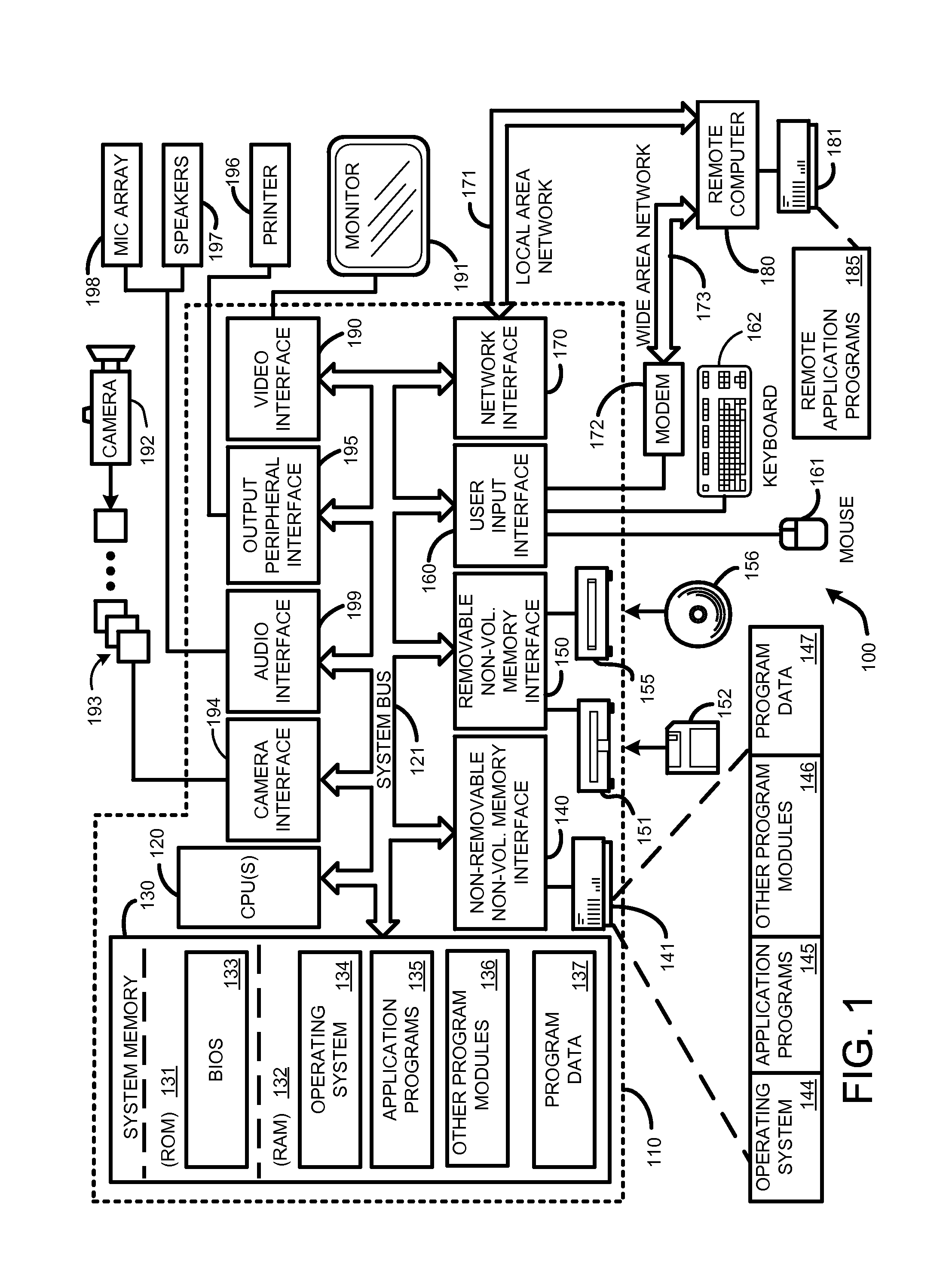
[0036]FIG. 1 illustrates an example of a suitable computing environment on which various embodiments and elements of an “Oblique Image Stitcher,” as described herein, may be implemented.

[0037]For example, FIG. 1 illustrates an example of a general computing system environment 100. The computing system environment 100 is only one example of a suitable computing environment and is not intended to suggest any limitation as to the scope of use or functionality of the invention. Neither should the computing environment 100 be interpreted as havi...


PUM


Abstract

An “Oblique Image Stitcher” provides a technique for constructing a photorealistic oblique view from a set of input images representing a series of partially overlapping views of a scene. The Oblique Image Stitcher first projects each input image onto a geometric proxy of the scene and renders the images from a desired viewpoint. Once the images have been projected onto the geometric proxy, the rendered images are evaluated to identify optimum seams along which the various images are to be blended. Once the optimum seams are selected, the images are remapped relative to those seams by leaving the mapping unchanged at the seams and interpolating a smooth mapping between the seams. The remapped images are then composited to construct the final mosaiced oblique view of the scene. The result is a mosaic image constructed by warping the input images in a photorealistic manner which agrees at seams between images.

Description

BACKGROUND[0001]1. Technical Field[0002]The invention is related to image stitching, and in particular, to a technique for constructing a photorealistic mosaiced image from a series of images of a scene.[0003]2. Related Art[0004]A number of conventional techniques have been developed to generate composite or stitched images to create an overall mosaic of a scene. The basic idea in generating such mosaic images is to take a plurality of partially overlapping photographic or video images in order to cover the entirety of the desired viewing space. These images are then aligned, warped, if necessary, and composited into complete panoramic mosaic images.[0005]In general, construction of these mosaic images is accomplished using any of a number of conventional image “mosaicing” or “stitching” algorithms that typically operate by identifying correspondences between the various images.[0006]To identify correspondences between two or more images, conventional image stitching schemes operate...

Claims


Application Information

Patent Timeline
Patent Type & Authority Patents(United States)
IPC IPC(8): G06K9/32G06K9/36G06V10/24
CPCG06K9/32G06T3/4038G06K2009/2045G06V10/16G06V10/24
Inventor STEEDLY, DREWSZELISKI, RICHARDUYTTENDAELE, MATTHEWCOHEN
Owner MICROSOFT TECH LICENSING LLC
Learn More