Method for assembling tiled detectors for ionizing radiation based image detection

a detector and ionizing radiation technology, applied in the field of imaging systems, can solve the problems of creating visible artifacts in the reconstruction image, complex assembly of detector tiles, and complicating the foregoing electrical connection of detectors and wafer materials, so as to facilitate multiple soldering steps, minimize edge gaps, and minimize visible artifacts

Inactive Publication Date: 2006-10-10
GE MEDICAL SYST GLOBAL TECH CO LLC +1
View PDF5 Cites 35 Cited by
  • Summary
  • Abstract
  • Description
  • Claims
  • Application Information

AI Technical Summary

Benefits of technology

[0006]The present technique provides a multi-tile detector and a process for assembling the multi-tile detector using a flexible structure and intermediate electrical connections. The present technique minimizes edge gaps between adjacent detector tiles by coupling the detector tiles to the flexible structure and then flexing the flexible structure to close the edge gaps. Intermediate electrical connections, such as interlayer solder bumps, also may be positioned in order to minimize visible artifacts associated with tiling of the detector tiles. The present technique also may use a plurality of soldering materials having different melting temperatures to facilitate multiple soldering steps that are nondestructive of previous soldering steps.

Problems solved by technology

For example, x-ray, computed tomography, positron emission tomography, nuclear, and gamma ray imaging detectors often use an ionizing photon detector material, such as Cadmium Zinc Telluride (CZT), Cadmium Telluride (CdTe), and various other crystalline semiconductor materials, which have size limitations due to a variety of production factors.
For example, imaging detectors using the CZT material generally require multiple tiles, because CZT crystals can only be grown in relatively small sizes due to yield problems with current technology.
Unfortunately, the tiling process tends to create gaps that create visible artifacts in the reconstructed image.
The assembly of detector tiles is also complicated by the need to connect the detector tiles electronically to their respective die, which then must be connected to the rest of the image receptor.
The different coefficients of thermal expansion of the detector and wafer materials also complicate the foregoing electrical connections, because the temperature restraints for assembly further limit the assembly size of the detector tiles.

Method used


Image

  • Method for assembling tiled detectors for ionizing radiation based image detection
  • Method for assembling tiled detectors for ionizing radiation based image detection
  • Method for assembling tiled detectors for ionizing radiation based image detection

Examples


Embodiment Construction

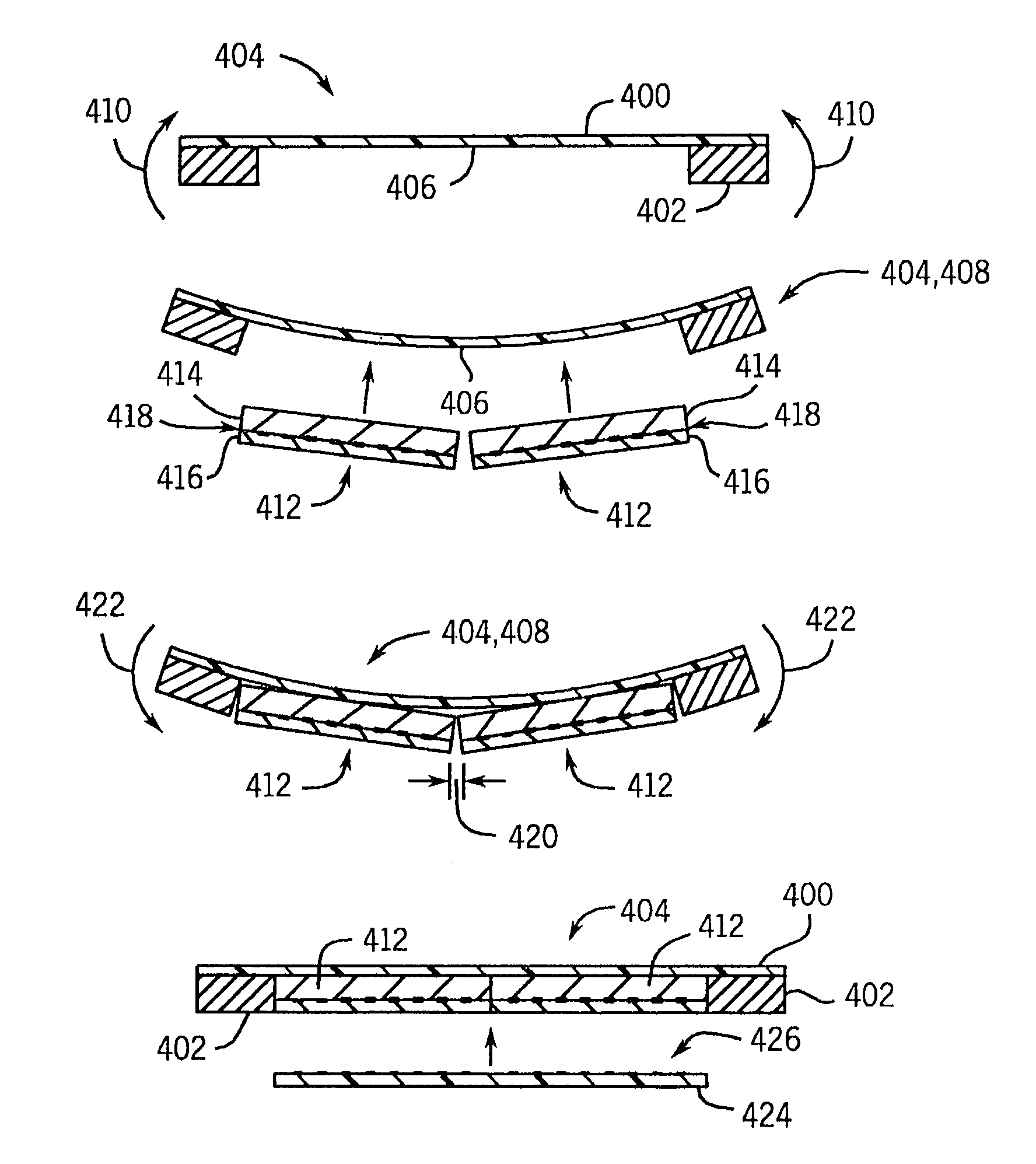
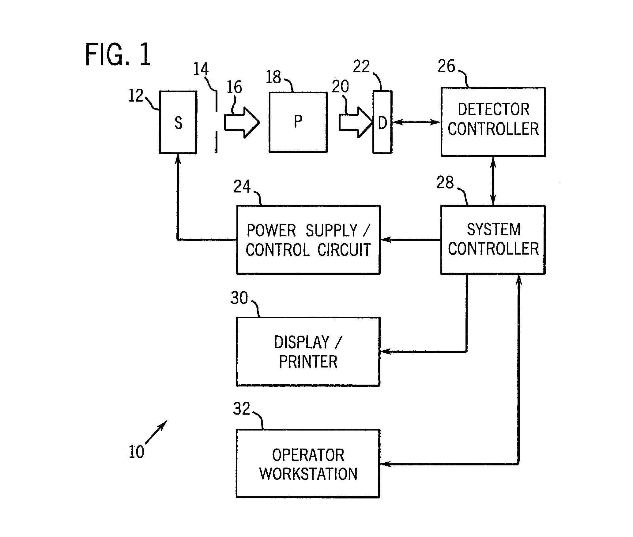
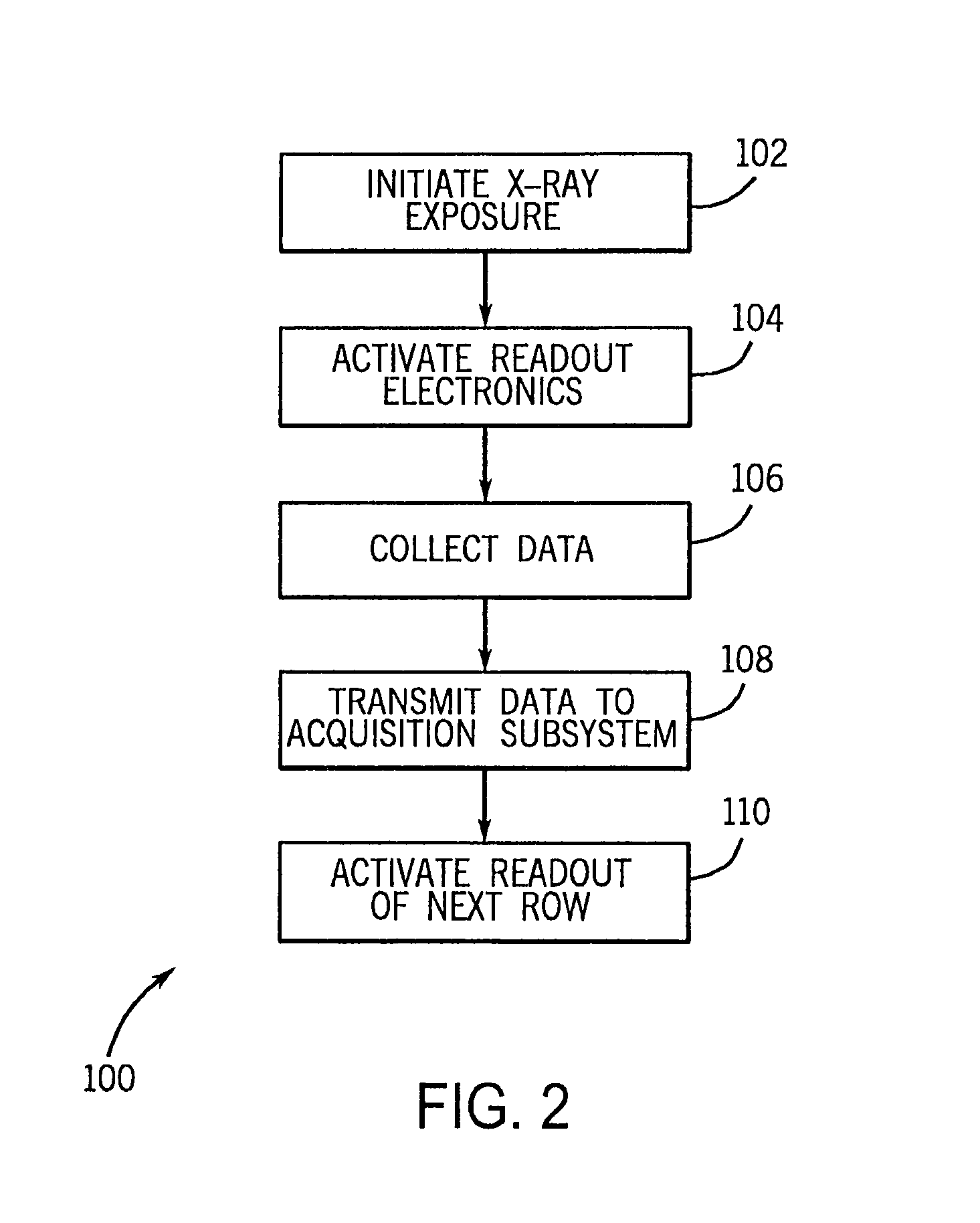
[0030]As described in detail below, the present technique relates to assembly and connection processes for imaging detectors made with multiple tiles of crystalline semiconductor material, such as Cadmium Zinc Telluride (CZT). However, the processes and detector assemblies described below are applicable to a wide variety of imaging systems, detector structures, and detector materials. For example, the present techniques are applicable to a variety of wide-bandgap semiconductors that may be used in direct conversion detectors for ionizing radiation, including CZT, Cadmium Telluride (CdTe), and Silicon CMOS. These assembly and connection processes produce imaging detectors having a plurality of tightly packed tiles and internally interconnected imaging layers, which may include ionizing photon detection layers, circuitry layers, and mechanical support layers. As follows, an exemplary imaging system is described with reference to FIGS. 1–2, followed by a detailed description of the for...


PUM

PropertyMeasurementUnit
thicknessaaaaaaaaaa
thicknessaaaaaaaaaa
flexibleaaaaaaaaaa

Abstract

The present technique provides a multi-tile detector and a process for assembling the multi-tile detector using a flexible structure and intermediate electrical connections. The present technique minimizes edge gaps between adjacent detector tiles by coupling the detector tiles to the flexible structure and then flexing the flexible structure to close the edge gaps. Intermediate electrical connections, such as interlayer solder bumps, also may be used to minimize visible artifacts associated with tiling of the detector tiles. The present technique also may use a plurality of soldering materials having different melting temperatures to facilitate multiple soldering steps that are nondestructive of previous soldering steps.

Description

BACKGROUND OF THE INVENTION[0001]The present invention relates generally to imaging systems, such as radiographic systems, and more particularly, to multi-tile detector assemblies used in such systems. Even more particularly, the present invention relates to a system and method for assembling detector tiles in a manner that minimizes or prevents visible artifacts associated with the tiling.[0002]Medical diagnostic and imaging systems are ubiquitous in modern health care facilities. Currently, a number of modalities exist for medical diagnostic and imaging systems. These include computed tomography (CT) systems, x-ray systems (including both conventional and digital / digitized imaging systems), magnetic resonance (MR) systems, positron emission tomography (PET) systems, ultrasound systems, nuclear medicine systems, and so forth. Such systems provide invaluable tools for identifying, diagnosing and treating physical conditions and greatly reduce the need for surgical diagnostic interve...

Claims


Application Information

Patent Timeline
Patent Type & Authority Patents(United States)
IPC IPC(8): H05K3/00G01T1/00A61B6/00A61B6/03G01T1/24H01L27/14H01L27/146H01L31/09
CPCH01L27/14658Y10T29/4913Y10T29/49117Y10T29/49789Y10T29/49133Y10T29/49144Y10T29/49169Y10T29/49124Y10T29/49126
Inventor VAFI, HABIBNEUMANN, DAVID C.PETRICK, SCOTT W.KAUTZER, JEFFREY A.
Owner GE MEDICAL SYST GLOBAL TECH CO LLC
Why Eureka
Try Eureka