

Home ultrasound system
a home ultrasound and ultrasound technology, applied in the field of medical equipment, can solve the problems of reducing the size and cost of portable general purpose ultrasound machines, reducing the portability of conventional imaging modalities, and reducing the size and cost of portable ultrasound machines. , to achieve the effect of improving portability and prolonging the battery li
- Summary
- Abstract
- Description
- Claims
- Application Information
AI Technical Summary
Benefits of technology
Problems solved by technology
Method used
Image

Examples
Embodiment Construction
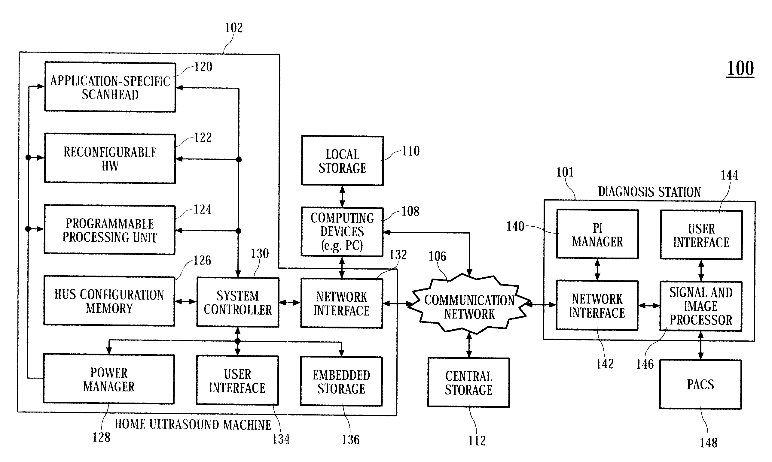
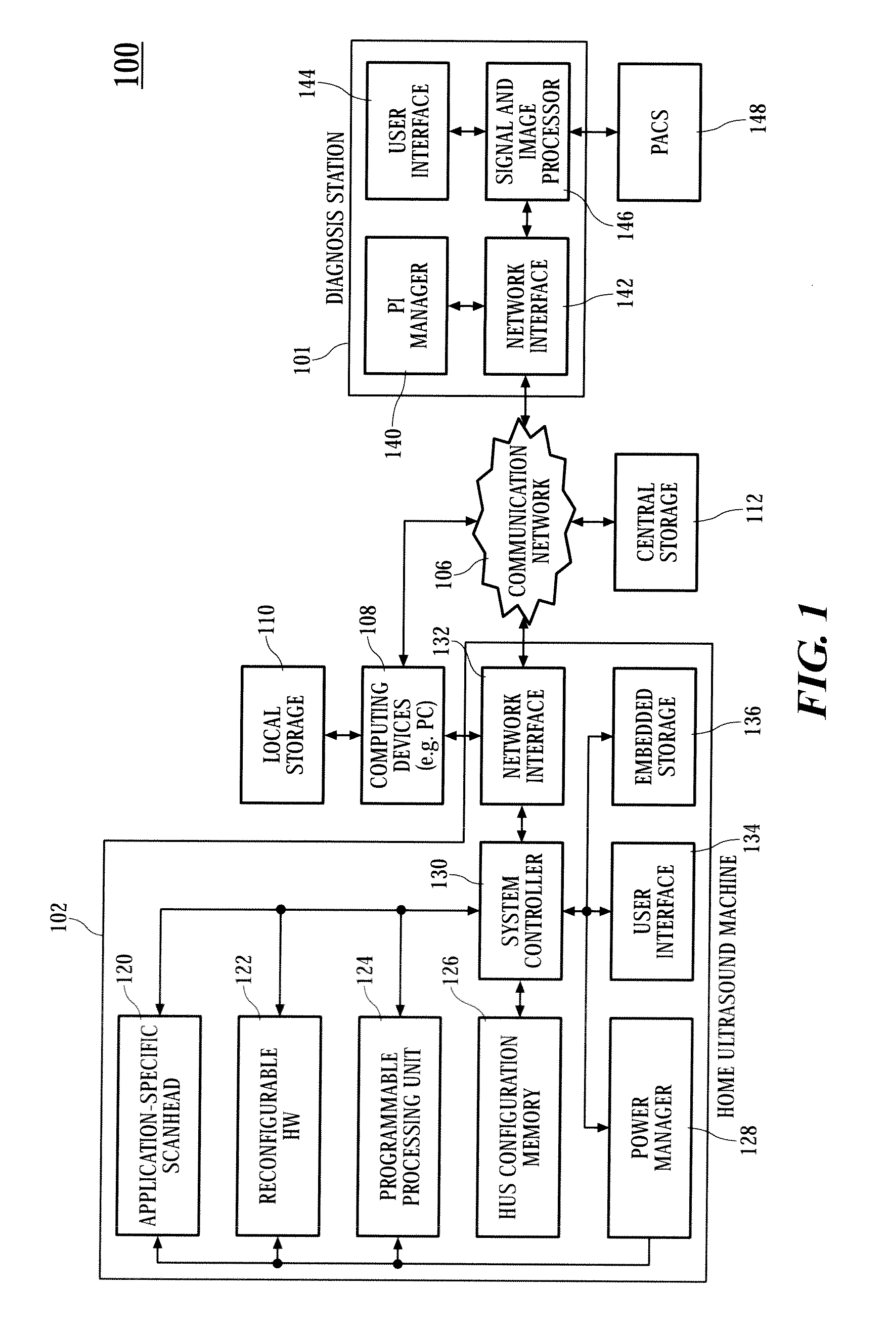
[0022]A home ultrasound system according to embodiments of the present invention may be capable of adapting to changing clinical needs and / or new applications, assisting non-experts to acquire clinically usable data / images, updating the examination protocols (i.e., scanning, image formation and analysis) from a remote location, supporting new clinical applications and / or adapting to changing clinical needs, supporting an efficient power management for improved portability and longer battery life, and supporting remote diagnosis, consultation and / or monitoring / screening. For some embodiments, the home ultrasound system includes a home ultrasound machine, external computing devices, local storage, central storage, and / or a remotely located diagnosis station. The home ultrasound machine may be used to scan a patient at home and acquire ultrasound data. The acquired ultrasound data may be transferred to the diagnosis station via a communication network. The home ultrasound machine may b...
PUM
 Abstract
Description
Claims
Application Information