
Two-piece cable tie suitable for use in an automated cable tie installation tool

a technology of automatic cable tie installation and cable tie, which is applied in the direction of hose connection, flexible elements, packaging, etc., can solve the problems of cable tie brittleness, cable tie rotation, and often broken wedge-shaped teeth, and achieves shallow height and width, increased grip, and resistance to cable tie rotation

Active Publication Date: 2010-08-24
PANDUIT
View PDF47 Cites 4 Cited by
  • Summary
  • Abstract
  • Description
  • Claims
  • Application Information

AI Technical Summary

Benefits of technology

The patent text describes a two-piece cable tie that solves various problems with conventional cable ties used in automated tools. The new cable tie has improved gripping of large or small bundles, can accommodate a diverse bundle size, and can securely fasten a near zero bundle size. It also has a thin center strap thickness and high side rails to maintain a cable tie height and profile that can be engaged by the tool. The technical effects of the new cable tie include improved grip, resistance to slippage and rotation, and a zero insertion force in the tip while maintaining sufficient strap rigidity and size for automated installation.

Problems solved by technology

There are many problems with conventional one-piece plastic cable ties used in automated tools.
One problem is that the wedge-shaped teeth often break during automated clamping by the tool.
This is particularly problematic when the cable ties are used in dry weather, which makes the cable ties brittle.
The problem can be caused by the extremely fast clamping action by the automated tool, and by the associated high tensioning force applied to the cable tie by the tool.
Another source of the problem is the abrupt stop of the cable tie after traveling at high speeds through the conveyance mechanism.
Another problem, particularly when using an automated installation tool, is ensuring a sufficiently low insertion force in the tip to enable the cable tie to be fed through the tool and have a strap end threaded through a strap accepting channel automatically without excessive resistance or binding.
Another problem, with or without use of an automated installation tool, is that traditional one-piece cable ties have limited loop tensile strength due to the use of a plastic locking device and the integrally formed wedge-shaped teeth, which reduce the cross-sectional thickness of the strap and cause inherent weaknesses in the design.
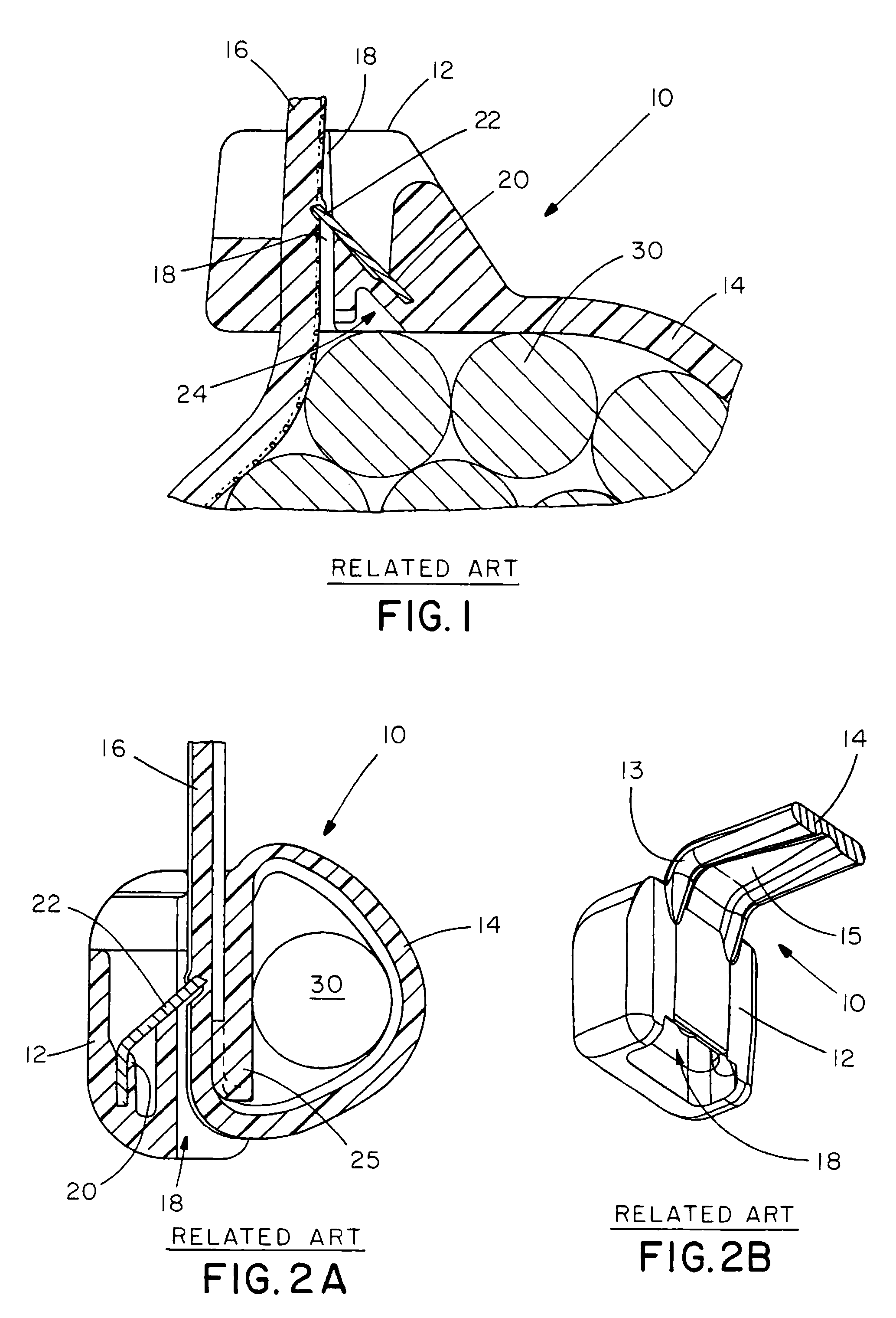
Similar problems exist in many two-piece cable ties, which sometimes encounter an inversion of the barbed locking device during application of high withdrawal forces.
Another problem with many conventional one-piece or two-piece cable ties in general is the inability of the cable tie to engage a bundle, such as loose wires, without slippage.
This is particularly problematic because the underside of the strap is able to rotate about the bundle even when reasonably tightened.

Method used


Image

  • Two-piece cable tie suitable for use in an automated cable tie installation tool
  • Two-piece cable tie suitable for use in an automated cable tie installation tool
  • Two-piece cable tie suitable for use in an automated cable tie installation tool

Examples


Embodiment Construction

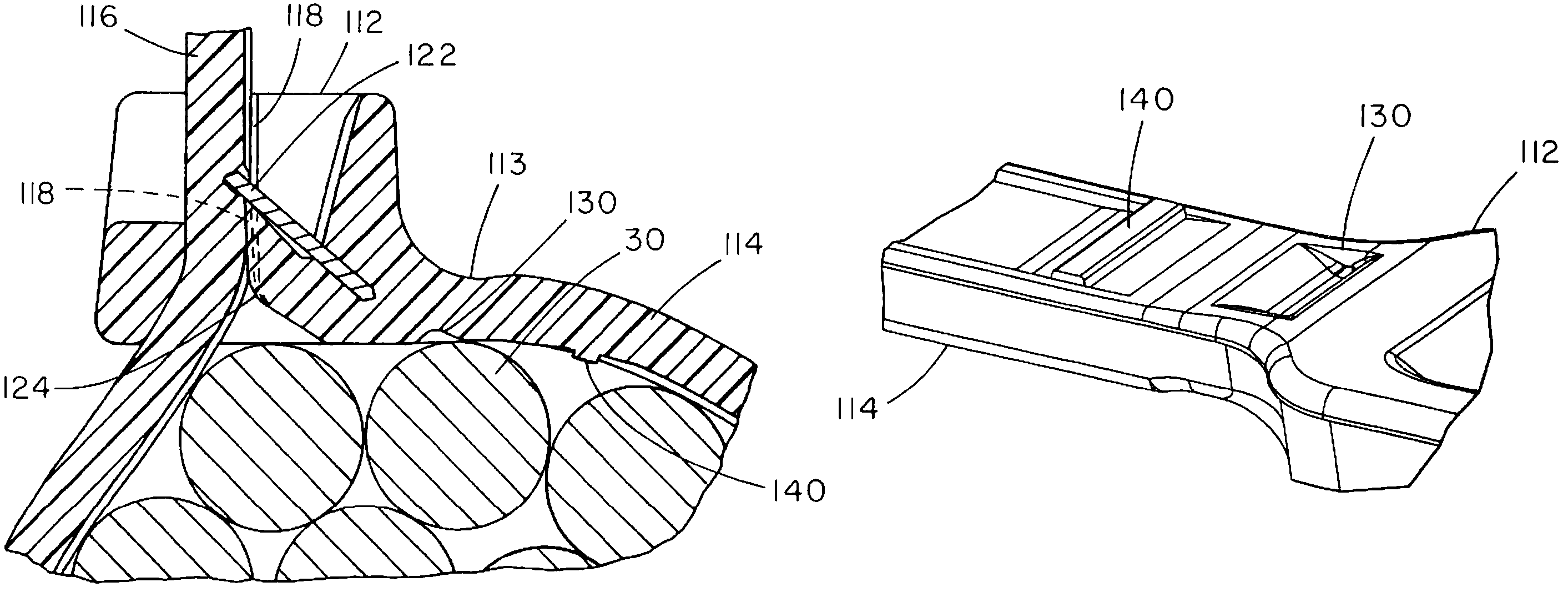
[0051]An exemplary embodiment of a two-piece cable tie suitable for use in an automated cable tie installation tool will be described with reference to FIGS. 5-15. FIGS. 5-7 show partial top, cross-sectional and bottom views, respectively, of an exemplary cable tie 100 having a head 112, strap 114, strap accepting channel 118, and a metal locking device 122 fixed in a locking device channel 120 so that an end of metal locking device 122 protrudes slightly into strap accepting channel 118. A reinforcement area 126 (best seen in FIG. 7) is provided immediately under the metal locking device 122. Reinforcing area 126 extends radially inward from the periphery of the strap accepting channel 118 to support an additional portion of the metal locking device and resist deformation or complete inversion of the metal locking device from excessive retraction forces applied to a cinched cable tie.

[0052]Rather than the typical substantially square edge profile of the strap accepting channel 118 ...


PUM


Abstract

A two-piece cable tie is provided that is capable of usage with an automated cable tie installation tool. The two-piece cable tie accommodates improved gripping of large or small bundles. By including a cored-out region near the neck, the cable tie can secure a near zero bundle size. By including a transverse pad on the bottom side of the cable tie strap near the cable tie head, the cable tie can be prevented from rotation relative to the bundle to which is it secured. A preferred cable tie strap has a wide recessed center section and high side rails that increase lateral clamping force. To resist barb inversion, the cable tie preferably includes a reinforcement area underneath the metal locking device when used with a strap having a recessed area. By maintaining relatively high side rails and a thin web section in the tip, the cable tie can achieve zero insertion force while maintaining sufficient strap rigidity and size to enable feeding of the strap through an automated cable tie installation tool.

Description

CROSS-REFERENCE TO RELATED APPLICATION[0001]This application claims priority to U.S. Provisional Application No. 60 / 680,988, filed May 13, 2005, the entirety of which is incorporated herein by reference.BACKGROUND OF THE INVENTION[0002]The invention relates to a two-piece barbed cable tie having improved bundling capabilities. The cable tie is suitable for use in an automated cable tie installation tool and can accommodate improved gripping of large or small bundles.[0003]Plastic cable ties are well known in the art. There are two main types: one-piece plastic cable ties having an integral plastic locking device; and two-piece cable ties that incorporate a metal locking device insert. Examples of one-piece cable ties include U.S. Design Pat. No. D389,051 to Caveney et al. and U.S. Pat. No. 4,632,247 to Moody et al. Although most one-piece cable ties are manually assembled and tightened, certain versions can be used in an automated cable tie installation tool, such as the one disclos...

Claims


Application Information

Patent Timeline
Patent Type & Authority Patents(United States)
IPC IPC(8): B65D67/02B65D63/00
CPCB65D63/1036Y10T24/1498
Inventor DEMIK, JONATHAN A.BROWNLEE, JAMES A.BERNARD, WILLIAM A.LEANNA, JERRY V.
Owner PANDUIT
Learn More