Mole trap

a technology of traps and traps, applied in the field of traps, can solve the problems of significant increase in the hand pulling force required to set traps

Active Publication Date: 2010-08-24
MILLER JAMES W +1
View PDF19 Cites 20 Cited by
  • Summary
  • Abstract
  • Description
  • Claims
  • Application Information

AI Technical Summary

Benefits of technology

[0003]The present invention is directed to an improved mole trap which provides all of the desirable features and advantages mentioned above and which will also remain in the ground when the spikes are driven into the ground. In accordance with the illustrated embodiment of the invention, a mole trap includes an inverted U-shaped frame having parallel spaced legs adapted to penetrate the ground, and a spike plate is supported by the legs for linear movement between an upper set position and a lower release position. A plurality of parallel spaced elongated spikes have upper end po...

Problems solved by technology

However, in order to increase the strike force and have the spikes move more quickly, it is necessary to use a ...

Method used


Image

  • Mole trap
  • Mole trap
  • Mole trap

Examples


Embodiment Construction

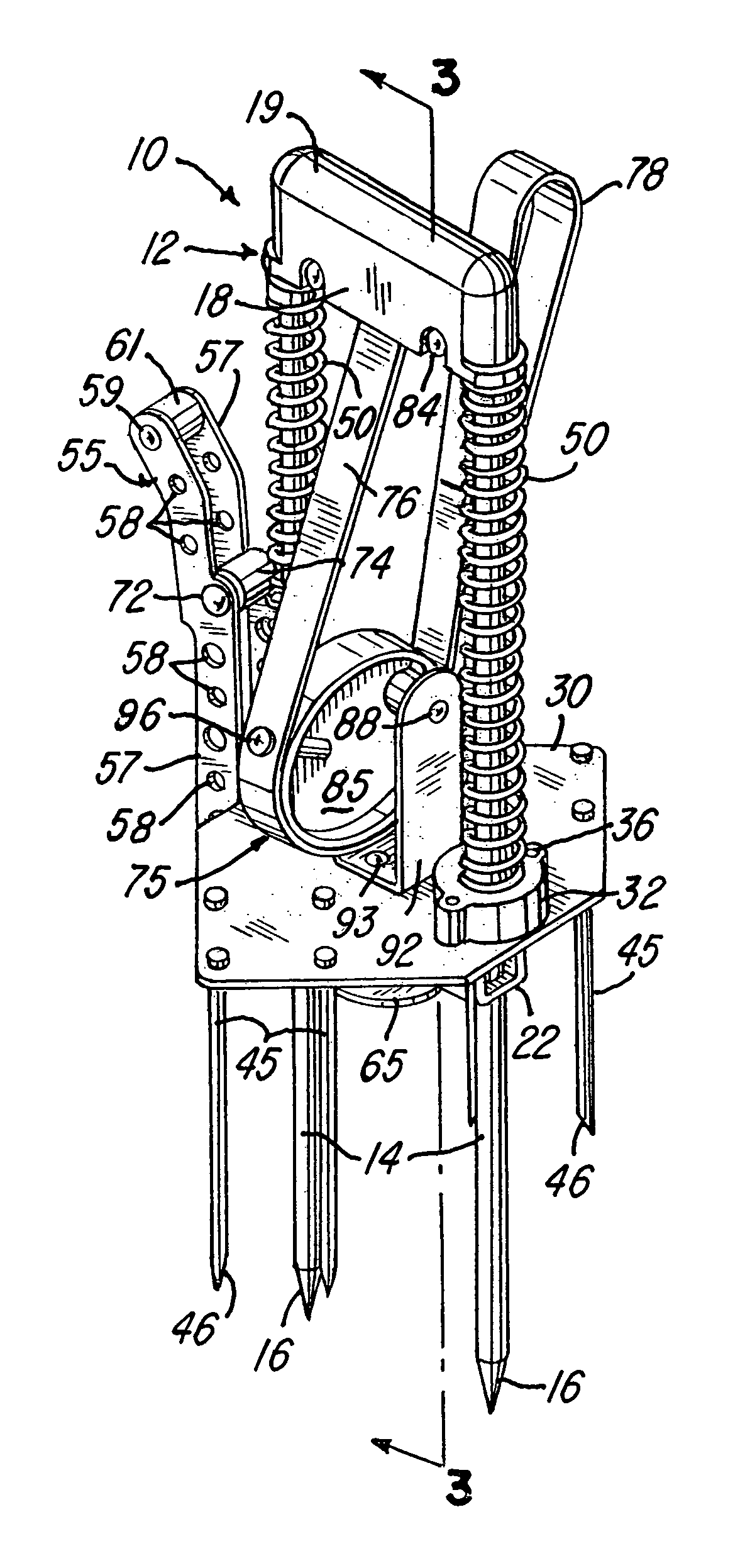
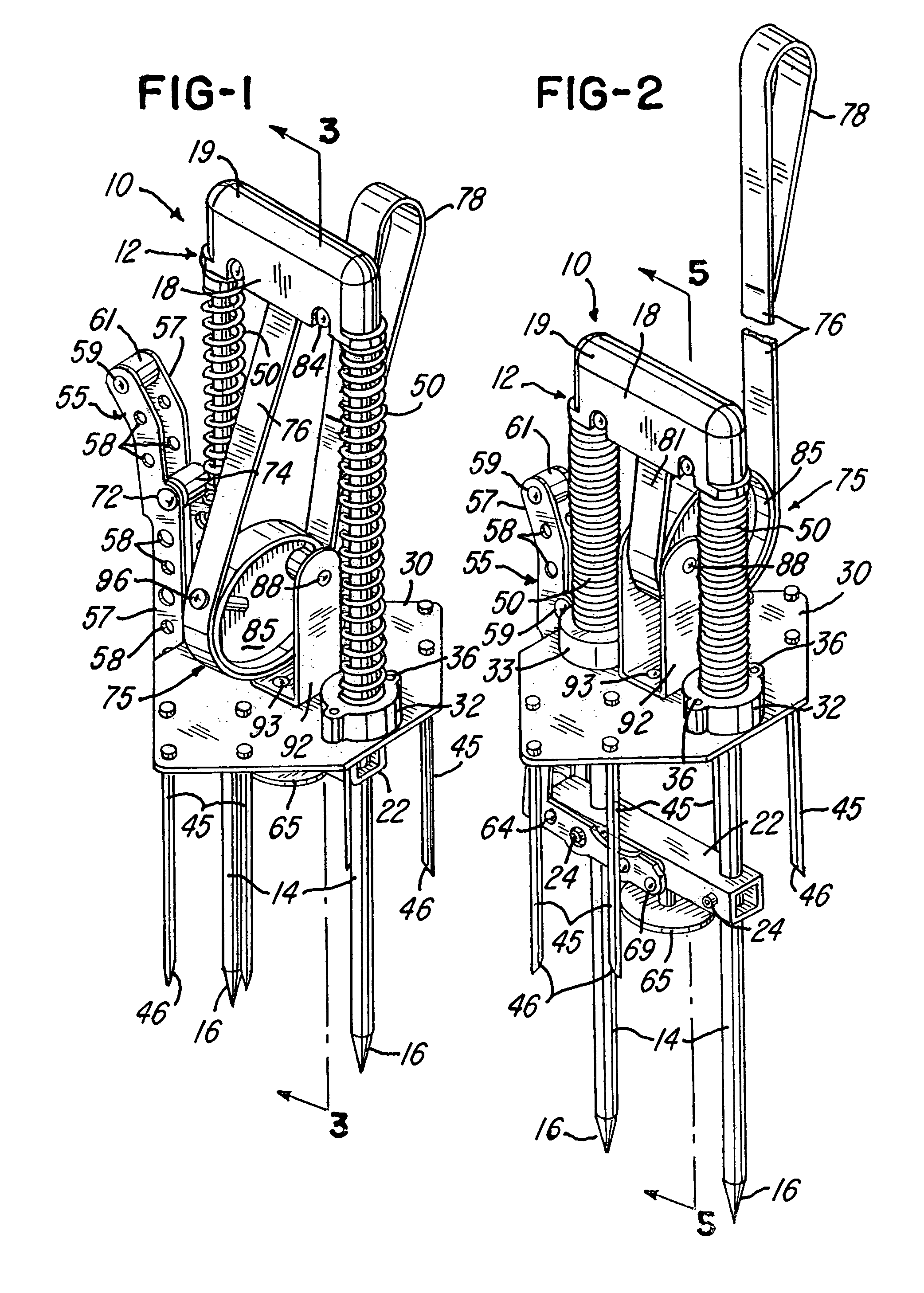
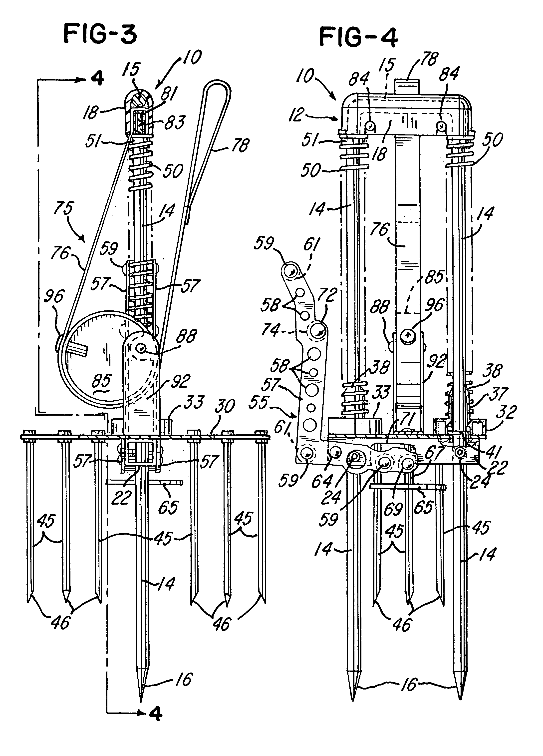
[0011]FIG. 1 shows a mole trap 10 constructed in accordance with the invention and which includes a rigid frame 12 formed by an inverted U-shaped steel rod having a pair of elongated parallel spaced legs 14 each having a pointed bottom end surface 16. The vertical legs 14 are integrally connected by a horizontal handle portion 15 which projects into a handle cover member 18 molded of a rigid plastics material. The handle cover member 18 has a rounded upper surface 19 to facilitate pressing the legs 14 into the ground. The legs 14 are also rigidly connected by tubular tie bar or stop member 22 secured to the legs 14 by Allen screws 24 which provide for adjusting the tie bar or stop member 22 vertically on the legs 14.

[0012]A flat sheet metal spike plate 30 carries a set of tubular molded plastic guide bushings 32 and 33, and the guide bushing 32 is secured to the spike plate 30 by a pair of screws extending upwardly through the spike plate and into holes 36 formed within the guide bu...


PUM


Abstract

A mole trap includes a steel rod frame having parallel spaced legs adapted to penetrate the ground on opposite sides of a mole hill or tunnel. The legs are integrally connected by a handle portion and also by a stop bar, and a spike plate having depending spikes is preloaded against the stop bar by compression springs mounted on the legs. An L-shaped latch lever is pivotally supported by the stop bar and supports a trip plate adapted to contact the ground where the mole tunnel has been depressed. The spike plate and spikes are retracted upwardly against the springs to a set position by pulling a flexible strap extending from the handle portion around a roller supported by the spike plate for rotation on an eccentric axis to provide a mechanical advantage. A roller on the latch lever automatically blocks the spike plate when elevated to the set position.

Description

BACKGROUND OF THE INVENTION[0001]The present invention relates to mole traps of the general type disclosed in expired U.S. Pat. No. 689,324, No. 1,330,622, No. 1,382,125, No. 2,086,826 and No. 3,013,358. As disclosed in these patents, an inverted U-shaped frame is formed from strap metal and has parallel spaced legs adapted to penetrate the ground. The legs support a spike plate having a plurality of parallel spaced spikes for movement between a lower extended position and an upper set position where the spike plate is temporarily retained by a latch member having a lower end engaging a trip lever pivotally supported by one of the legs. The spike plate and spikes are pulled upwardly to the set position by a metal hand strap which is surrounded by a coil spring urging the spike plate and spikes downwardly on the legs.[0002]In a mole trap such as disclosed in the above-mentioned patents, it has been found desirable to have a number of steel spikes which are driven into the ground quic...

Claims


Application Information

Patent Timeline
IPC IPC(8): A01M23/30
CPCA01M27/00
Inventor MILLER, JAMES W.MILLER, SCOTT W.
Owner MILLER JAMES W
Why Eureka
Try Eureka