Back orthosis and orthotic method

a back brace and orthotic technology, applied in the field of back brace and orthotic method, can solve the problems of not providing integrated support or allowing the movement of the lumbar piece laterally in either direction, prior art fails to provide a back brace that provides a self-adjustable level of effective, etc., and achieves the effect of greater for

Active Publication Date: 2010-07-01
CROPPER DEAN +1
View PDF101 Cites 90 Cited by
  • Summary
  • Abstract
  • Description
  • Claims
  • Application Information

AI Technical Summary

Benefits of technology

[0006]Thus, the present invention is directed to a spinal orthosis that provides an easy and effective means to reduce or eliminate back pain.
[0007]The present invention is alternately or additionally directed to a spinal orthosis—for chronic, acute, pre-operative, and / or post-operative persons—that can effectively be applied and adjusted by the wearer.
[0008]The present invention is alternately or additionally directed to a spinal orthosis with system components that broaden the brace's application such as allowing modification of a brace generally from a lumbo sacral orthosis (“LSO”) to a thoracic lumbo sacral orthosis (“TLSO”) or an osteoarthritic (“OA”) brace, or both.
[0009]The present invention is also directed to an orthotic method that provides an easy and effective means to reduce or eliminate back pain.
[0010]The present invention is alternately or additionally directed to an orthotic method—for chronic, acute, pre-operative, and / or post-operative persons—that allows effective application and adjustment by the wearer.

Problems solved by technology

Prior attempts to provide back support through a mechanical advantage fail to provide optimal pain relief or account for the shortcomings of providing only pure circumferential pressure as a factor in back pain stress, however.
U.S. Pat. No. 7,001,348 B1, entitled “Double Pulley Body Brace”, discloses a single one-piece body panel and double pulley system, but likewise fails to provide integrated support or allow movement of its lumbar piece laterally in either direction.
Hence, the prior art fails to provide a back brace that provides a self-adjustable level of effective pressure directly to the spinal region of the lower back that is integrated with the tightening and loosening afforded by a mechanical advantage.

Method used


Image

  • Back orthosis and orthotic method
  • Back orthosis and orthotic method
  • Back orthosis and orthotic method

Examples


Embodiment Construction

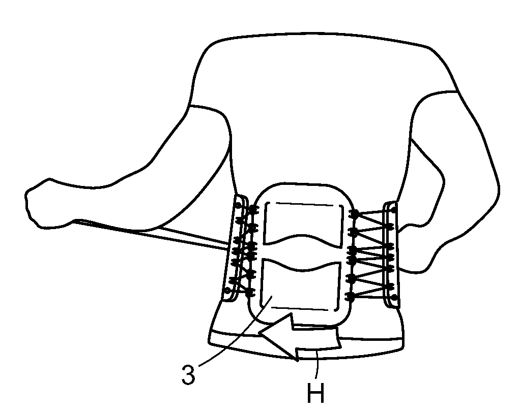
[0049]As illustrated in the accompanying drawings and discussed in detail below, one aspect of the present invention is directed to a back orthosis that, when used, provides high circumferential compression to the lower torso with a high level of mechanical advantage. The back orthosis of this aspect nevertheless also applies a continued direct, adjustable amount of active support especially to the lower back, which can be finely tuned by lateral adjustment specifically to a particular area of pain.

[0050]In one embodiment, the back orthosis of the present invention provides a lumbo sacral orthosis (“LSO”) 1. Referring to FIGS. 1 and 2, LSO 1 generally includes rigid separate rear lumbar panel 3, which is attached to each of right side attachment member 5 and left side attachment member 7 by respective separate right and left cords 9 and 10 to form a circumferentially attachable orthosis about a wearer's waist and torso. Right and left tensioning handles 11 and 13 can be used by any ...


PUM


Abstract

A lumbar orthosis that includes first and second, separate, opposing and mating front attachment panels; and a separate, laterally adjustable, rigid lumbar compression piece configured for positioning only at the rear of a wearer, wherein pulling of a cord causes the brace both circumferentially to tighten and to concentrate compression and pressure of the separate, laterally adjustable, rigid lumbar compression piece directly and especially upon a spinal region of a wearer's back with the aid of a mechanical advantage dependant upon a number of apertures through which the cord or cords pass. An orthosis and method for correcting lumbar and thoracic back pain and disorders is also disclosed.

Description

FIELD OF THE INVENTION[0001]The present invention relates to a back brace and orthotic method. More particularly, the present invention relates to a spinal orthosis and orthotic method that provides an adjustable level of pressure to the lower back and high circumferential compression to the lower torso, particularly at the abdomen.BACKGROUND OF THE INVENTION[0002]Back braces are intended to alleviate or eliminate pain and suffering caused by various disorders along a person's spine. Some disorders more specifically relate to the lumbar region (vertebrae L1-L5), while others more specifically to the thoracic lumbar region (vertebrae T5 through S1). Others still stem at least in part from osteo-degenerative causes. The dynamic, integrated nature of various portions of the spine—as well as the many others variables that affect such disorders—make the occurrence of such disorders dependant on a large number of factors.[0003]Several attempts to alleviate back pain include the applicatio...

Claims


Application Information

Patent Timeline
Patent Type & Authority Applications(United States)
IPC IPC(8): A61F5/00
CPCA61F5/024A61F5/028A61F5/30
Inventor CROPPER, DEANCROPPER, TANNER
Owner CROPPER DEAN
Why Eureka
Try Eureka