Retractor and methods of use

a technology of retraction device and retraction chamber, which is applied in the field of surgery, can solve the problems of not allowing a surgeon or other qualified professional easy access to the surgical site, and the current device does not address the clearing of tissue obstructions at deeper levels in the surgical site, so as to achieve easy installation, and improve the effect of surgical site clearan

Active Publication Date: 2010-08-24
ALPHATEC SPINE INC
View PDF7 Cites 76 Cited by
  • Summary
  • Abstract
  • Description
  • Claims
  • Application Information

AI Technical Summary

Benefits of technology

[0011]Embodiments of the invention relate to a tissue retractor for use by medical personnel (i.e., doctor) for spinal surgery, and may be used to expose spinal structures during spinal surgery. Such embodiments, for example, enable minimal disruption of spinal muscles and sensitive elements of the posterior, lateral, and anterior regions of the spine. Furthermore, some embodiments of the invention are capable of performing in the thoracolumbar region, as well as sacral and cervical regions of the spine, or any other regions.
[0012]Some embodiments of the invention include an open halo structure to form a rigid platform. This open halo may allow for instruments to be manipulated from inside to outside of the halo. The halo may include openings for attaching, for example, a rigid arm to secure the halo, and thus the instrument (according to some embodiments), in place.
[0013]In some embodiments of the invention, retraction blades are included in various lengths, configurations, and with various features to accommodate different applications for the retractor. The blades may be used to form a closed exposure to the surgical site and can be installed easily while at this position. The blades may be constructed of various materials to aid in radio translucency, strength, flexibility, and integration with anatomy etc.
[0014]Some embodiments of the invention may also include a retraction mechanism which allows a squeezing motion to expand the retractor and expose the desired spinal elements. Such a ratcheting mechanism allows for incremental expansion of the retraction blades. In that regard, the expansion load may be transmitted from the handle to the blades by a cable, which may be woven through the mechanism. The characteristics of the cable allow loads to be compounded and increased. Specifically, in the cable system, using a system of pulleys, the cable may be directed through the rigid halo structure.

Problems solved by technology

Many current devices do not permit a surgeon or other qualified professional easy access to a surgical site, and moreover, current devices do not address the clearing of tissue obstructions at deeper levels in the surgical site.

Method used


Image

  • Retractor and methods of use
  • Retractor and methods of use
  • Retractor and methods of use

Examples


Embodiment Construction

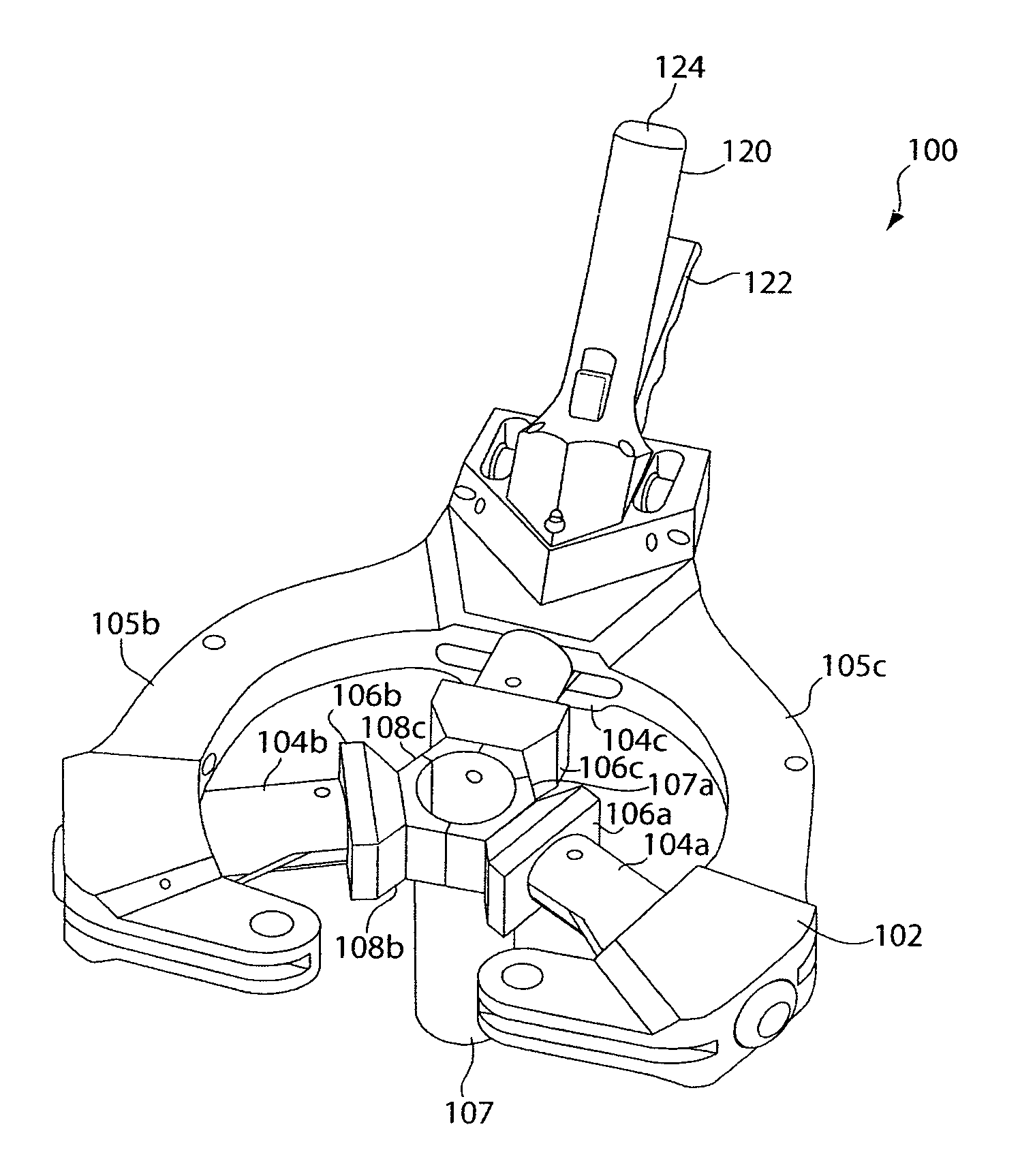
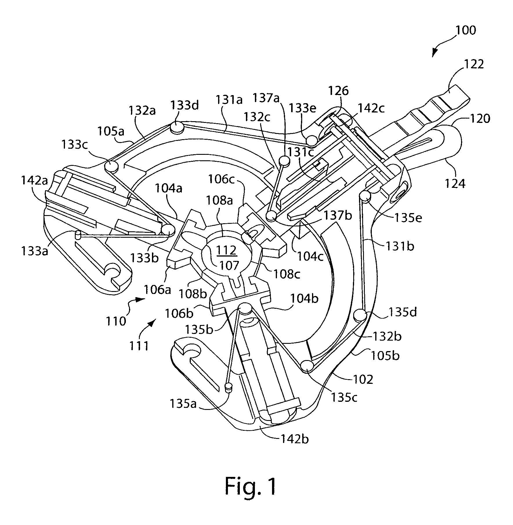
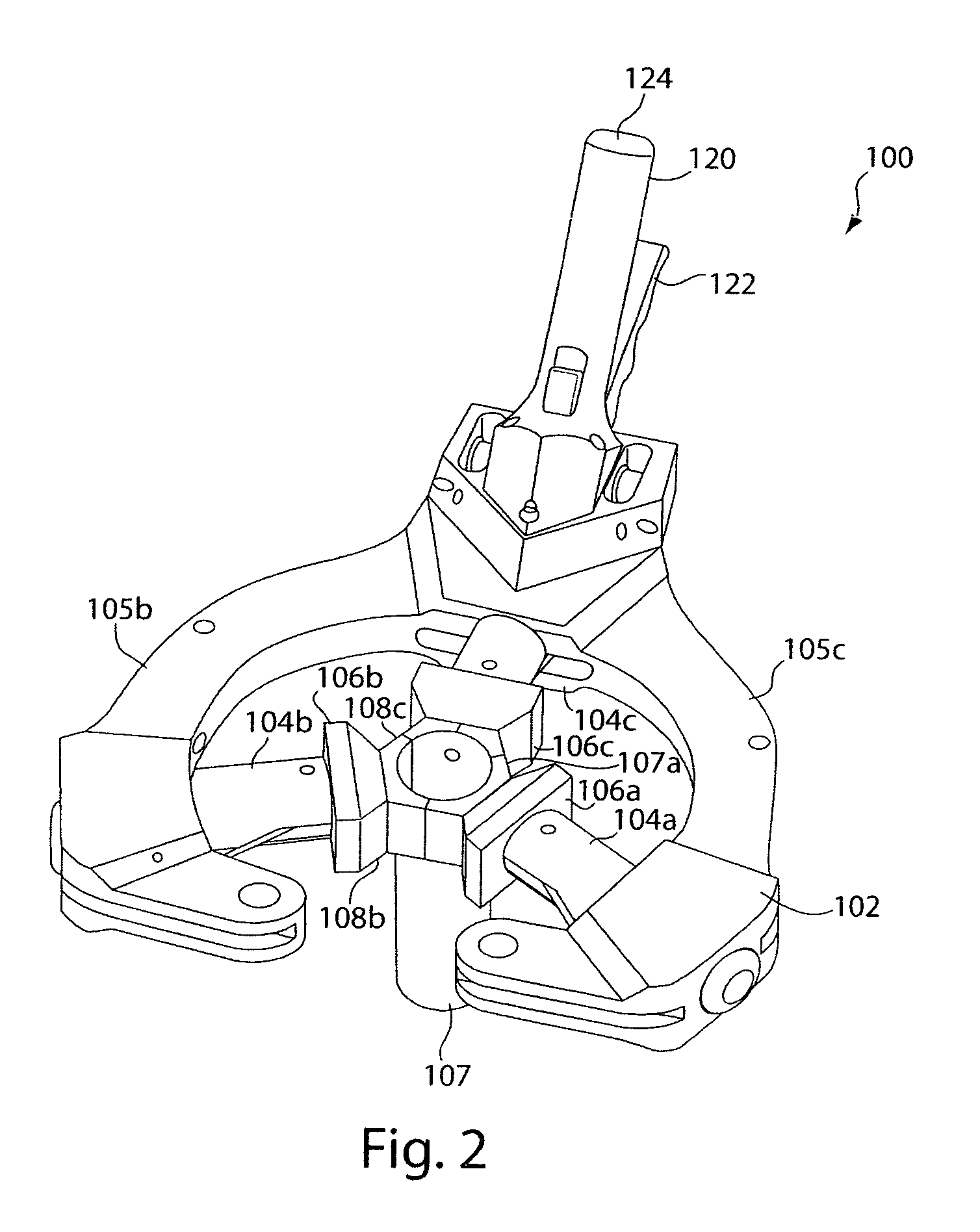
[0022]FIG. 1 is a perspective, cross-sectional bottom view of a retractor device 100 which includes a housing 102, a handle assembly 120, three blade holders 104(a, b, c), and three blades 108(a, b, c). As can be understood by one skilled in the art, there can be any number of blade holders 104 and blades 108.

[0023]The housing 102 further includes a hollow interior or a halo 110 formed by the sides 105(a, b). The sides 105(a, b) are joined together at the handle assembly 120 and form a gap 111 opposite the handle assembly 120. As can be understood by one skilled in the art, the sides 105 can be joined together at all times and not form any gaps. The hollow interior 110 further includes a center 112 that is located substantially in the center of the hollow interior 110.

[0024]As shown in FIG. 1, the blade holders 104 are configured to be slidably coupled to the housing 102, which allows the blade holders 104 to be capable of translational movement within the same plane as the plane of...


PUM


Abstract

A retractor is disclosed. The retractor includes a housing, at least one blade holder slidably coupled to the housing, and an actuator handle to control sliding movement of the blade holder. The blade holder and the actuator handle hold at least one blade.

Description

CROSS-REFERENCE TO RELATED APPLICATIONS[0001]The present application claims priority to U.S. Provisional Application No. 60 / 725,007, to Hutton, filed Oct. 7, 2005, and titled “Retractor” and incorporates its entire disclosure herein by reference.BACKGROUND OF THE INVENTION[0002]1. Field of the Invention[0003]The present invention relates generally to the field of surgery, and more specifically to a retractor device which may be used during spinal surgery for exposure of a surgical site.[0004]2. Background of the Invention[0005]There is a significant number of people that suffer spinal disorders that may require spinal surgery and / or intervention. Such surgeries typically require exposure and access to the internal spinal elements. Through the exposure, the surgeon may remove, add, medicate, and / or modify pathological elements to remedy the spinal disorder.[0006]Conventional treatment may also include traction, either with a halter or with Crutchfield type tongs, followed by an appli...

Claims


Application Information

Patent Timeline
Patent Type & Authority Patents(United States)
IPC IPC(8): A61B1/32
CPCA61B17/02A61B17/0293
Inventor HUTTON, CLARK
Owner ALPHATEC SPINE INC
Why Eureka
Try Eureka