Thermal printer and method of controlling the same

a technology of thermal printers and printers, applied in the field of thermal printers, can solve the problems of inability to apply to the thermal printer used for issuing sales receipts to customers, difficult to handle by users, and inability to print data input quickly, etc., to achieve the effect of rapid printing and data inpu

Active Publication Date: 2010-08-24
TOSHIBA TEC KK +1
View PDF35 Cites 11 Cited by
  • Summary
  • Abstract
  • Description
  • Claims
  • Application Information

AI Technical Summary

Benefits of technology

[0010]It is an object of the present invention to provide a highly practical thermal printer that can rapidly print printing data input from the outside on both surfaces of a thermal paper sheet.

Problems solved by technology

When an amount of printing data input from the outside is large, a thermal paper sheet on which the data is to be printed becomes long and hence it is difficult to handle by a user.
However, processing similar to that used in a copying machine takes too much time, and therefore cannot be applied to a thermal printer used for issuing a sales receipt to a customer at, e.g., a store.

Method used


Image

  • Thermal printer and method of controlling the same
  • Thermal printer and method of controlling the same
  • Thermal printer and method of controlling the same

Examples


first embodiment

[1] First Embodiment

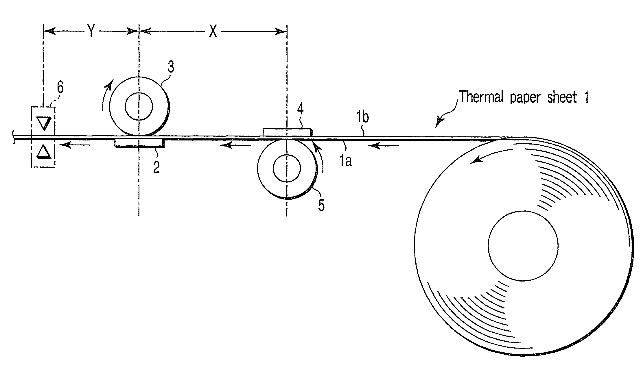
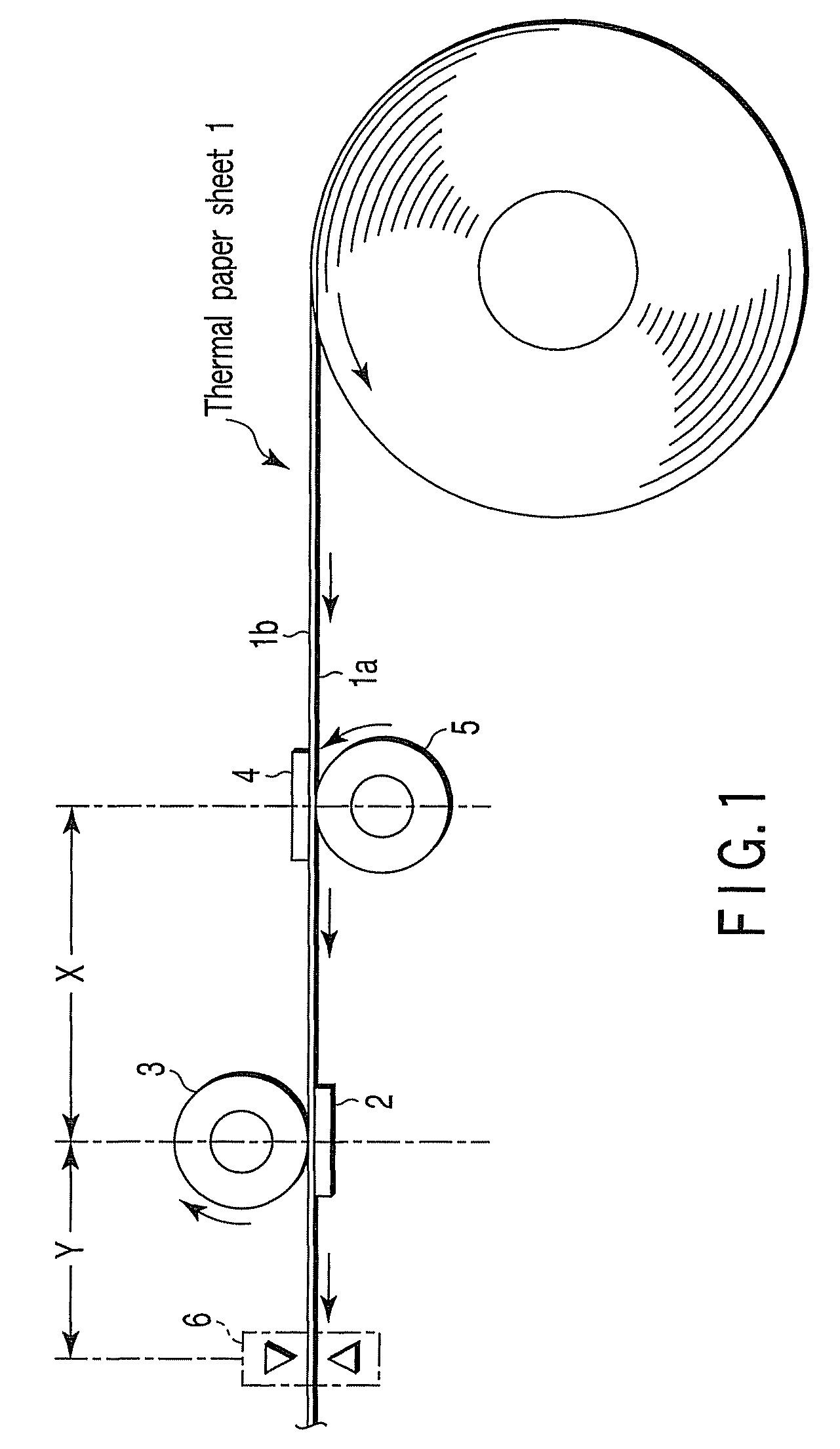
[0048]A first embodiment according to the present invention will now be described hereinafter with reference to the accompanying drawings. First, FIG. 1 shows a structure of a primary part.

[0049]Reference numeral 1 denotes a thermal paper sheet. The thermal paper sheet 1 has heat-sensitive layers on both surfaces thereof, i.e., a first surface (which will be referred to as a front surface) 1a and a second surface (which will be referred to as a rear surface) 1b having a front-and-rear relationship, respectively. A proximal end side of the thermal paper sheet 1 is rolled up in such a manner that the front surface 1a becomes an inner side, and a distal end side is fed in a direction indicated by an arrow in the drawing by a later-described paper feed mechanism 22. The heat-sensitive layer is made up of a material that is colored into, e.g., black or red when heated to a predetermined temperature or above.

[0050]A first thermal head 2 that comes into contact with the...

second embodiment

[2] Second Embodiment

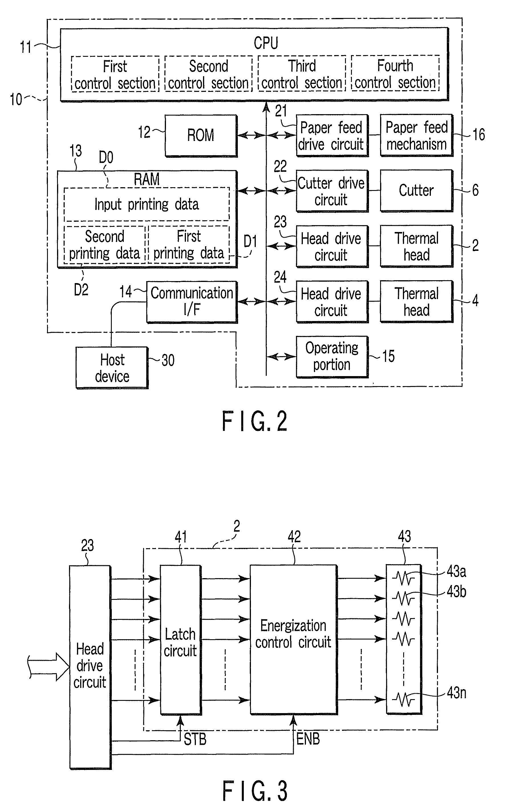
[0101]A second embodiment according to the present invention will now be explained with reference to the accompanying drawings. The basic structure is the same as that shown in FIG. 1, thereby omitting an explanation thereof. FIG. 11 shows a control circuit of a thermal printer main body 10.

[0102]A CPU 11 has the following means (11) to (14) as primary functions.

[0103](11) A retrieving section of retrieving printing data Dm corresponding to a previously registered keyword from printing data D0 input from an external host device 30. The keyword is at least one item included in printing data to be printed on one surface of a thermal paper sheet 1.

[0104](12) A registering section of registering the keyword in accordance with an operation of an operating portion 15.

[0105](13) A first control section of dividing the input printing data D0 into first printing data D1 for a first thermal head 2 including the retrieved printing data Dm and second printing data D2 for a ...

third embodiment

[3] Third Embodiment

[0123]A third embodiment according to the present invention will now be explained with reference to the accompanying drawings. The basic structure is the same as that shown in FIG. 1.

[0124]Moreover, as shown in FIGS. 20 and 21, a first thermal head 2 has operation disabled regions with predetermined widths T1a and T1b where sufficient heating at the time of printing is impossible at one end and the other end, and has an operation enabled region T1 between both the operation disabled regions. A second thermal head 4 also has operation disabled regions with predetermined widths T2a and T2b where sufficient heating at the time of printing is impossible at one end and the other end, and has an operation enabled region T2 between both the operation disabled regions.

[0125]FIG. 17 shows a control circuit of a thermal printer main body 10.

[0126]That is, a detection unit 17 is connected with a CPU 11. The detection unit 17 optically or mechanically detects a width PW of t...


PUM


Abstract

A thermal paper sheet having heat-sensitive layers on a first surface and a second surface having a front-and-rear relationship is prepared. A first thermal head which comes into contact with a front surface of this thermal paper sheet and a second thermal head which comes into contact with a rear surface 1b of the same are provided. Further, printing data input from the outside is divided into first printing data and second printing data. The thermal heads are driven in accordance with the printing data.

Description

CROSS-REFERENCE TO RELATED APPLICATIONS[0001]This application is based upon and claims the benefit of priority from prior Japanese Patent Applications No. 2006-151695, filed May 31, 2006; No. 2006-152577, filed May 31, 2006; No. 2006-153608, filed Jun. 1, 2006; and No. 2006-153609, filed Jun. 1, 2006, the entire contents of all of which are incorporated herein by reference.BACKGROUND OF THE INVENTION[0002]1. Field of the Invention[0003]The present invention relates to a thermal printer that uses a thermal paper sheet having heat-sensitive layers on both surfaces thereof, and a method of controlling the same.[0004]2. Description of the Related Art[0005]A thermal paper sheet used in a thermal printer has a heat-sensitive layer on one surface thereof. In accordance with this structure, a thermal printer has one thermal head, and prints printing data input from the outside on one surface of a thermal paper sheet by using the single thermal head. The printed thermal paper sheet is cut by...

Claims


Application Information

Patent Timeline
Patent Type & Authority Patents(United States)
IPC IPC(8): B41J2/32
CPCB41J2/355B41J3/54B41J3/60
Inventor BABA, SUMIOYAMADA, SATOSHITAGUCHI, HIROYUKI
Owner TOSHIBA TEC KK
Why Eureka
Try Eureka