Pallet-forming roller-belt conveyor

a roller belt conveyor and pallet technology, applied in the direction of conveyor parts, packaging, transportation and packaging, etc., can solve the problems of high back line pressure, belt tension increase, and accelerate roller belt wear

Active Publication Date: 2010-08-31
LAITRAM LLC
View PDF33 Cites 11 Cited by
  • Summary
  • Abstract
  • Description
  • Claims
  • Application Information

AI Technical Summary

Problems solved by technology

But, because contact between the rollers and the bearing surface is not frictionless, roller wear accelerates and belt tension increases.
Furthermore, because the rotation of the oblique rollers pushes the articles forward as well, accumulated articles would experience high back line pressure.

Method used


Image

  • Pallet-forming roller-belt conveyor
  • Pallet-forming roller-belt conveyor
  • Pallet-forming roller-belt conveyor

Examples


Embodiment Construction

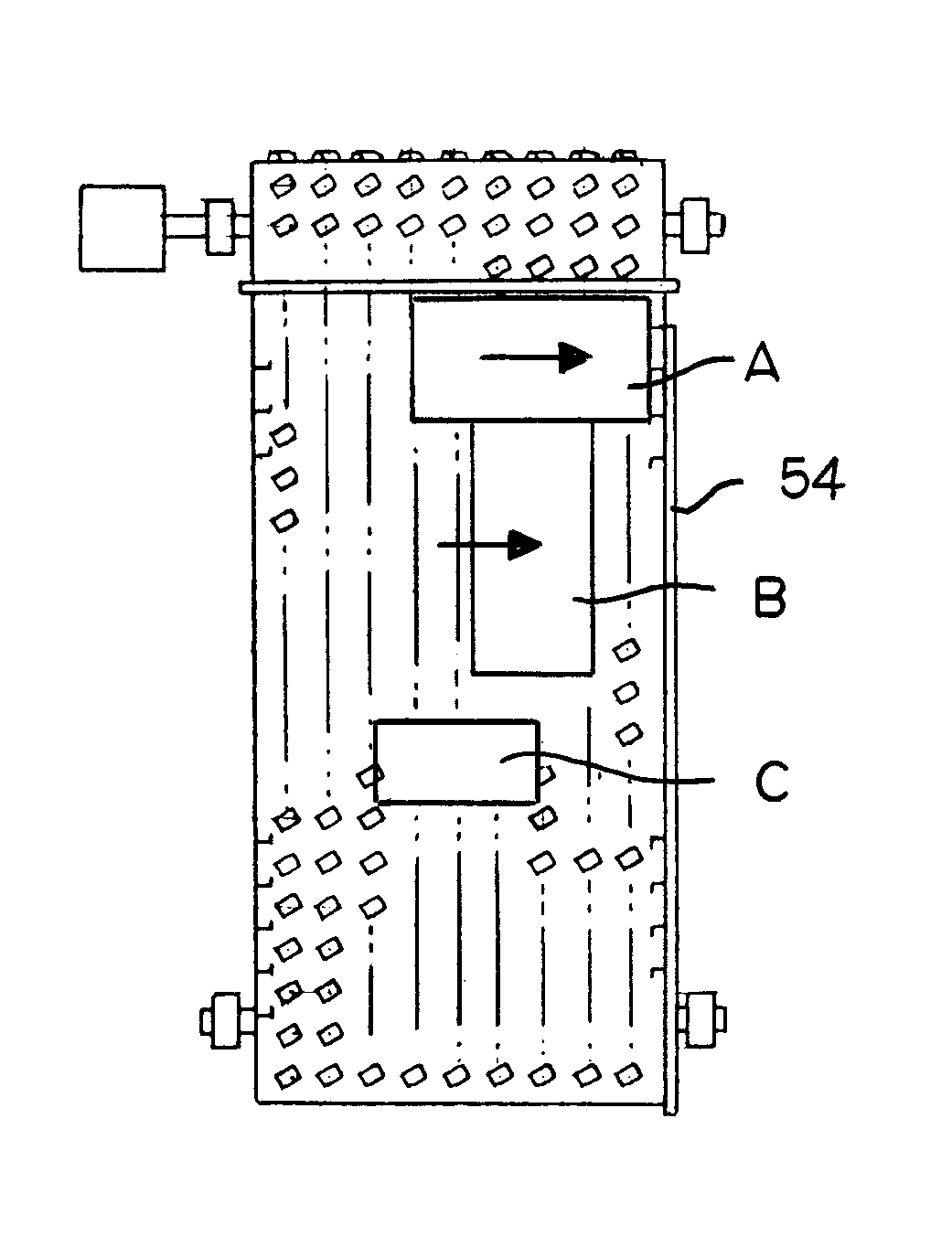
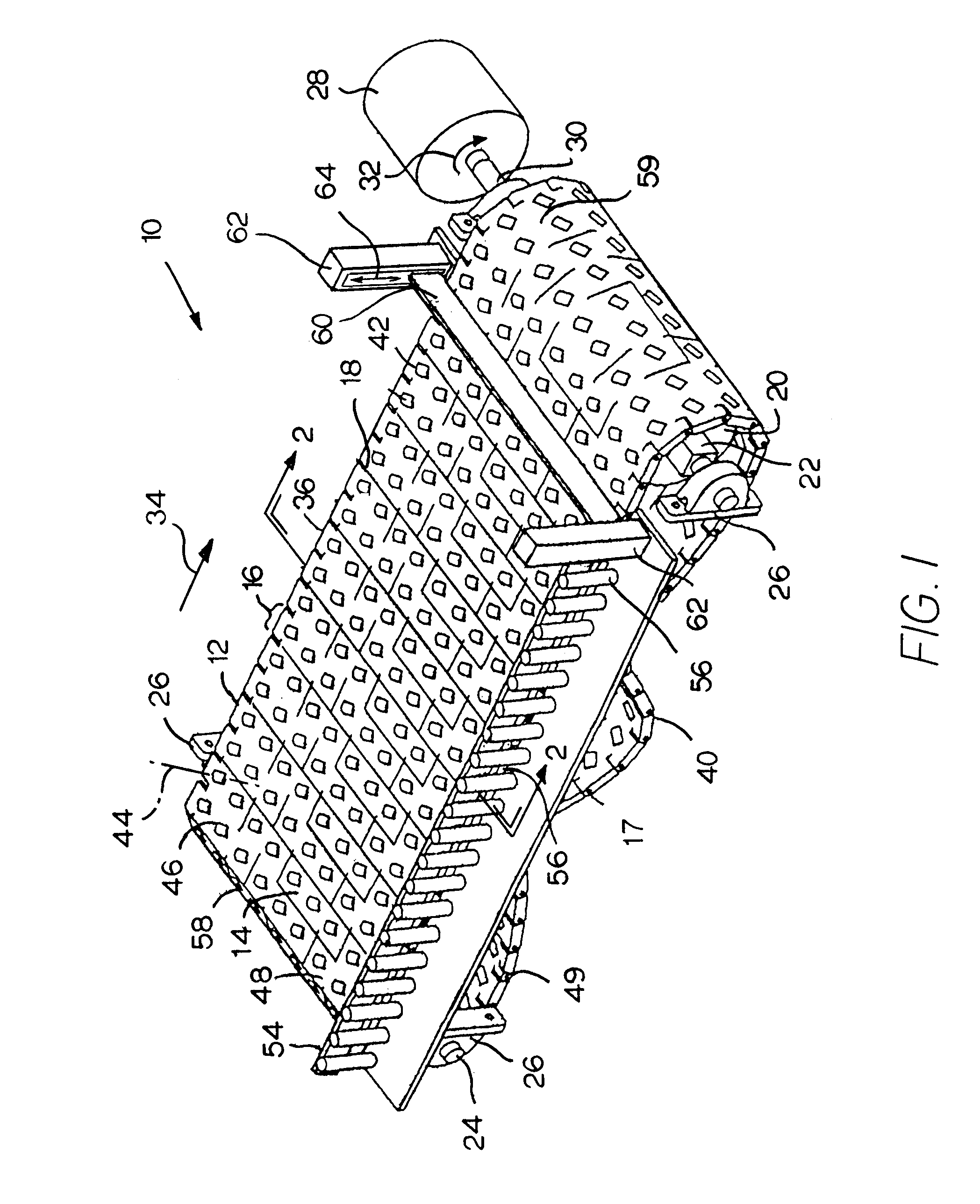
[0015]FIG. 1 shows a conveyor 10 embodying features of the invention including a conveyor belt 12, such as a modular roller-top conveyor belt. The conveyor belt shown is a modular conveyor belt made up of belt modules 14 arranged in a series of rows 16. The rows are connected together by hinge pins 17 at hinge joints 18 that allow the belt to articulate about drive and idler sprockets 20 at each end of the conveyor. The belt forms an endless loop trained around a drive shaft 22 and an idler shaft 24. The shafts are supported at their ends in bearing blocks 26 mounted on a conveyor frame (not shown for simplicity). A motor 28 is coupled to the drive shaft 22 to drive the belt. As the motor's output shaft 30 rotates as shown by arrow 32, the belt advances in a direction of belt travel 34.

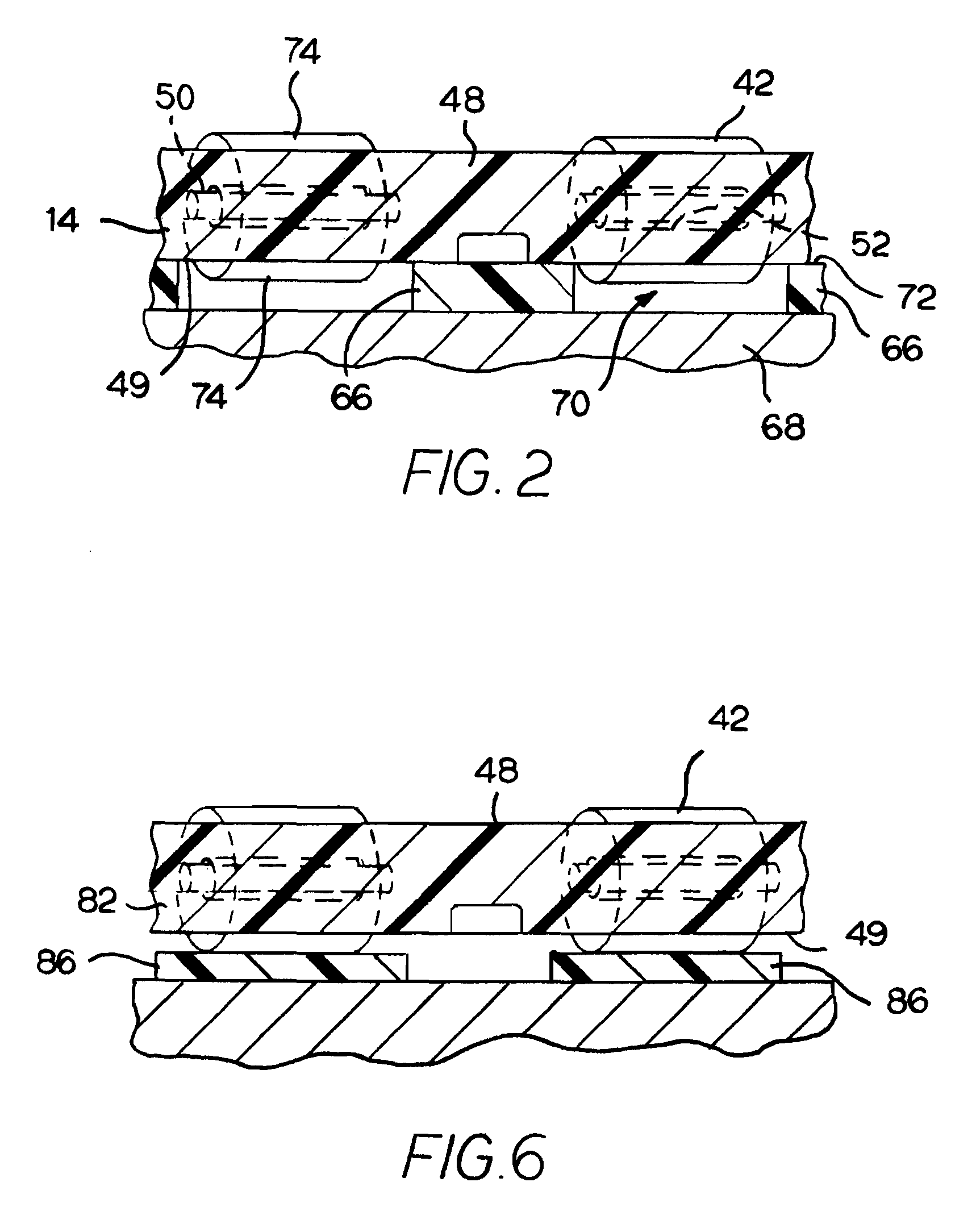
[0016]A portion of the belt loop, in particular the upper, article-conveying portion 36 in FIG. 1, is supported on a carryway 38 (FIG. 2). The belt returns from the drive sprockets via a returnway 40 ...


PUM


Abstract

A conveyor using a roller belt with rollers arranged to rotate on oblique axes to urge articles toward a side guide. The conveyor includes an oblique-roller belt supported on a carryway for running in a direction of belt travel. Rollers extend above an outer conveying surface of the belt without contact with the carryway. Each roller rotates on an axis oblique to the direction of belt travel and intersects the side guide downstream of the roller's position. A retractable stop is movable to and from a blocking position along the carryway. In the blocking position, the stop blocks the conveyed articles from advancing in the direction of belt travel. The rollers underlying the blocked articles rotate as the belt runs by contact with the articles. The rotating rollers provide a component of force to the blocked articles directed toward the side guide to push the articles against the side guide or other articles as they accumulate under low pressure upstream of the stop. The conveyor may be used to register articles single file against the side guide or to group the articles for palletizing. For palletizing applications, an infeed conveyor feeds articles onto the belt at the side opposite the side guide.

Description

CROSS-REFERENCE TO RELATED APPLICATIONS[0001]This application is a continuation of U.S. patent application Ser. No. 12 / 186,854, entitled “Roller-Belt Conveyor for Moving Articles across the Conveyor,” filed Aug. 6, 2008, now U.S. Pat. No. 7,617,923, which is a continuation of U.S. patent application Ser. No. 11 / 766,209, entitled “Methods for Accumulating, Moving, and Palletizing Articles,” filed Jun. 21, 2007, now U.S. Pat. No. 7,537,104, which is a continuation of U.S. patent application Ser. No. 10 / 908,326, entitled “Roller-Belt Conveyor for Accumulating and Moving Articles Laterally across the Conveyor,” filed May 6, 2005, now U.S. Pat. No. 7,249,671, all of which are entirely incorporated herein by reference.BACKGROUND[0002]The invention relates to power-driven conveyors and, more particularly, to methods for using a conveyor belt with obliquely oriented rollers to accumulate, move, or palletize articles.[0003]Many material-handling applications require that conveyed articles be...

Claims


Application Information

Patent Timeline
Patent Type & Authority Patents(United States)
IPC IPC(8): B65G47/26
CPCB65G17/24B65G47/086B65G47/244B65G47/22B65G2207/30B65G47/28
Inventor RIDDICK, DAVID W.LALLY, BRETT A.COSTANZO, MARK
Owner LAITRAM LLC
Why Eureka
Try Eureka