Automatic sled plate comb bonding machine and using method

A technology of sled boards and bonding machines, which is applied in the direction of veneer presses, plywood presses, and the joining of wooden veneers, which can solve the problems of material waste, easy breakage, and inability to use sled wood, etc.

Inactive Publication Date: 2016-12-21
SHANDONG UNIV
View PDF10 Cites 2 Cited by
  • Summary
  • Abstract
  • Description
  • Claims
  • Application Information

AI Technical Summary

Problems solved by technology

[0004] But the existing comb machines are all combs in the horizontal direction, the height of the opening is 80mm, and the thickness of the center of the sled plank is only about 30mm, so the number of combs is too small, the product is not firm after bonding, and it is easy to break; Yes, the current wood butt joint machine is a flat wood butt joint machine, which is only suitable for wood with a thickness greater than 8.5mm and is flat, and cannot be used for sled wood with a curved surface
The waste during the sled processing is wedge-shaped wood whose thickness varies from 30mm to 0.5mm from one end to the other. If the existing flat material butt joint machine on the market is used, only by thickening the tail end to 8.5mm can a better butt joint effect be achieved. , which will result in a great waste of material

Method used


Image

  • Automatic sled plate comb bonding machine and using method
  • Automatic sled plate comb bonding machine and using method
  • Automatic sled plate comb bonding machine and using method

Examples


Embodiment Construction

[0043]Reference will now be made in detail to the exemplary embodiments, examples of which are illustrated in the accompanying drawings. When the following description refers to the accompanying drawings, the same numerals in different drawings refer to the same or similar elements unless otherwise indicated. The implementations described in the following exemplary examples do not represent all implementations consistent with the present invention. Rather, they are merely examples of apparatuses and methods consistent with aspects of the invention as recited in the appended claims.

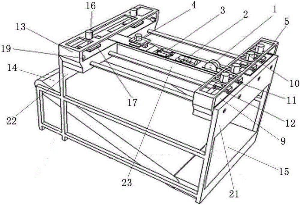
[0044] Take the axial direction of the workbench 23 as the longitudinal direction, and the direction perpendicular to the axial direction of the workbench 23 as the transverse direction.

[0045] see figure 1 , which shows the basic structure of the automatic ski comb bonding machine provided by the embodiment of the present invention.

[0046] The automatic sled board comb bonding machine prov...


PUM


Abstract

The invention relates to an automatic sled plate comb bonding machine and a using method. The automatic sled plate comb bonding machine comprises a first mounting rack and a second mounting rack, wherein a worktable is fixedly arranged between the first mounting rack and the second mounting rack, a transporter is movably arranged at one end close to the first mounting rack; a bonding vehicle is movably arranged at one end close to the second mounting rack, and the transporter and the bonding vehicle respectively move along the axis direction of the worktable; the bonding vehicle comprises a pressing block which is obliquely mounted; the pressing block is used for crimping woods; a cutting device, a combing device, a gluing device and an adhesive pressing device are sequentially arranged along the axis of the worktable; the cutting device is arranged at one end close to the first mounting rack; the adhesive pressing device is arranged at one end close to the second mounting rack; and the combing device comprises a combing knife; and the combing knife reciprocates along the vertical direction. The automatic sled plate comb bonding machine combines functions such as cutting, combing, gluing and bonding into a whole, and the woods are pressed in an oblique axis manner by adopting vertical combs, so that bonding is firm.

Description

technical field [0001] The invention relates to the technical field of wood processing equipment, in particular to an automatic sled board comb-tooth bonding machine and a use method thereof. Background technique [0002] With the scarcity of forest resources, the effective and rational utilization of wood is an urgent problem to be solved in various wood application industries. For example, in the production and processing of sled boards, it is inevitable that some wooden boards will appear. If the finished sled boards can be made into finished sled boards through subsequent recycling, this will not only realize the effective use of wood resources, save materials, but also further reduce production. cost. Among them, the combination of comb machine and bonding machine can lengthen the short wood, and the strength and hardness of the lengthened wood board can meet the needs of processing and production compared with the original long wood. [0003] At present, the technolo...

Claims


Application Information

Patent Timeline
Patent Type & Authority Applications(China)
IPC IPC(8): B27C9/00B27D1/10B27D3/00B27F1/16B27G11/00B27M3/22
CPCB27C9/00B27D1/10B27D3/00B27F1/16B27G11/00B27M3/22
Inventor 宁淑荣范开禹陈原
Owner SHANDONG UNIV
Why Eureka
Try Eureka